


All installations and services must be performed by qualified service personnel.
16
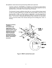
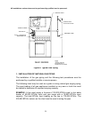
4. Flue/Vent Connector
:
• Either drill a starter hole in the inducer or use a self-tapping screw to
mount the flue pipe to the inducer. Failure to follow these instructions
may damage the inducer.
• All vents and vent connectors must fit tightly to avoid air leaks.
• The MHA1/MDA1 series furnaces must not be installed with vent
damper.
The connection of this furnace to the vent system, shall be in accordance with
the local building codes, the vent manufacturers instructions and part 10,”
Venting of Equipment”, of the National Fuel Gas Code, NFPA 54/ANSI Z223.1-
2002, or latest edition.
These venting tables also include venting combinations, which apply to common
venting arrangements of two or more appliances. These requirements as well as
all the installation requirements outlined in this manual for an MHA1/MDA1
series furnace must be followed when an MHA1/MDA1 furnace is common
vented with another Category I gas appliance.
See also Section II, J, 2, of this manual “Replacing an Existing Furnace from a
Common Vent” for information on testing the proper operation of appliances in a
common vent.
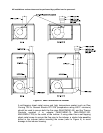
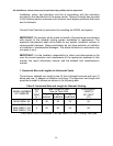
The vent connector must be galvanized or stainless steel metal pipe and must be
a 3 in. in diameter for the MHA1/MDA1-50 and 4 in. in diameter for the
MHA1/MDA1-75, MHA1/MDA1-100 and MHA1/MDA1-125. The MHA1/MDA1-75,
MHA1/MDA1-100 and MHA1/MDA1-125 are supplied with a 3 in. to 4 in. adapter
as a transition from the inducer to the 4 in. vent size (see figure 4). No size
reduction is permissible. For minimum and maximum vent lengths, see Venting
Tables for Category I appliances in the National Fuel Gas Code
, NFPA 54/ANSI
Z223.1-2002, or latest edition.