


All installations and services must be performed by qualified service personnel.
27
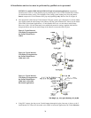
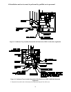
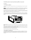
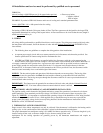
4. If the furnace is used in connection with an air conditioning evaporator coil, the furnace must be installed parallel
with or on the upstream side of the coil, to prevent condensation in the heat exchanger. If the evaporator coil is
installed with a parallel flow arrangement, dampers or other means to control flow of air should be installed to
prevent chilled air from entering the furnace. If such a device is manually operated, it must be equipped with a means
to prevent operation of either the furnace or air conditioner unless it is in the full heat or cool position.
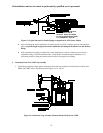
We recommend that the outlet duct be equipped with a removable access panel to allow for visual inspection of the
heat exchanger to check for leakage or to allow for insertion of a probe sampler in the air stream. This removable
access cover should be attached to ensure there is no air leakage.
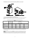
5. The duct system shall be sized for the maximum CFM requirement of the installation whether it is for heating or
cooling. Two common rules for heating and cooling follow:
A. 400 CFM (1200 BTU's) per ton of cooling is required.
B. 14 CFM of heating per 1000 BTU's of furnace output based on its steady state efficiency and a 55° to 85°
temperature rise.
EXAMPLE: Heating output of a furnace is 100,000 BTU/HR
100,000 BTU x 14 cfm = 1400 CFM
1000 BTU
Air conditioning installed is 4 tons x 400 CFM = 1600 CFM or 48,000 BTU’s. NOTE: The duct system must be
sized for the larger CFM requirement for cooling. If only 3 tons 36,000 BTUs of cooling x 400 CFM = 1200 CFM
was installed, the duct would have to be sized for the 1400 Cfm heating requirement.
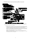
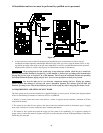
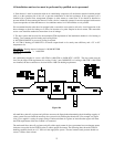
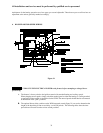
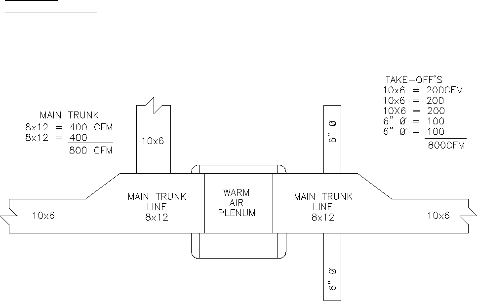
Figure 18A
All trunk lines, take-offs, registers and grill-free areas must be figured when determining the air handling capacity of
a duct system. One can obtain the necessary duct system size by utilizing the chart below. (For example, see Figure
18A.) Use a supplier’s catalog for proper sizing of outlet and return air registers to insure that the register will meet
the CFM requirements of the run to which it is connected.
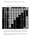
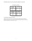
The main trunk lines, take offs, registers and grills of the supply return air duct system must have an adequate square
inch area to move the desired CFM in order to achieve proper movement. The following chart shows the CFM air
handling capability based on a 0.1” SP loss in the supply duct system. The total external static pressure should not
exceed .2 inches water column.