


All installations and services must be performed by qualified service personnel.
9
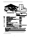
D. General Requirements For Venting Models CHB1 / CDB1
The CHB1 / CDB1 furnace venting system must be installed by a qualified service person in accordance with local
installation codes and these instructions. In the absence of applicable local codes, conform to the National Fuel Gas
Code, NFPA 54 /ANSI Z223.1-2002, or latest edition thereof.
Installation shall, at least, conform to the following requirements.
1. The exhaust vent / combustion air intake terminations specified by Thermo Products, in this manual, shall
be used.
2. All plastic pipe and pipefittings sourced to complete the exhaust vent and air intake systems shall be
constructed of rigid PVC (polyvinyl chloride) thermoplastic. All components shall have a wall
thickness equivalent to Schedule 40 series materials.
In addition, all sourced PVC components shall be listed by a nationally recognized testing agency (e.g.
NSF, UL, etc.) as conforming to one (1) or more of the following design standards.
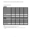
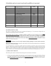
PVC Pipe Designation Design Standard
Cellular Core ASTM-F891
DWV (Drain-Waste-Vent) ASTM-D2665
Schedule 40 ASTM-D1785
3. The exhaust vent pipe and combustion air pipe shall be at least as large as the exhaust vent / air intake pipe
specified by Thermo Products. Size reduction is never permissible. The required exhaust vent / air intake
pipe sizes are:
• nominal 2-inch diameter IPS, Schedule 40 series, PVC thermoplastic pipe, for models CHB1–50 / –
75 & CDB1–50 / –75, or
• nominal 3-inch diameter IPS, Schedule 40 series, PVC thermoplastic pipe, for models CHB1–100 / –
125 & CDB1–100 / –125.
4. The furnace model series CHB1 / CDB1 shall not be common vented with any other appliance, including
those burning solid fuels.
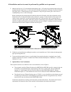
5. All horizontal runs of exhaust vent pipe shall slope upward at least ¼ inch per foot from the outlet of the
furnace (for the model series CHB1), or the outlet of the drain tee (for the model series CDB1) to the vent
termination, beyond the outside wall. This slope will permit proper drainage of the condensate.
Horizontal runs of air intake pipe shall slope downward at least ¼ inch per foot from the outlet of the last
elbow or last horizontal run, before exiting the wall, to the intake termination beyond the outside wall. This
slope will permit proper drainage of any precipitation that enters the intake pipe.
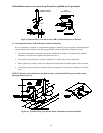
6. The exhaust vent pipe shall be supported at every joint (no more than 4-feet between supports) to
prevent pipe blockage due to condensate trapped at a local low point, or sag, in the vent system.
7. The maximum permissible length of piping (consisting of a combination of straight pipe and a
corresponding number of elbows) permitted is:
• 75 equivalent feet, for the exhaust vent system, and
• 70 equivalent feet, for the combustion air intake system
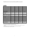
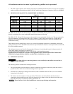
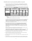
8. The maximum quantity of Schedule 40 series, type DWV thermoplastic pipe elbows allowed in each system
is listed in Table 2. When counting pipe elbows, all elbows used in the exhaust vent or combustion air