


All installations and services must be performed by qualified service personnel.
20
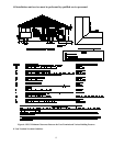
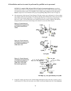
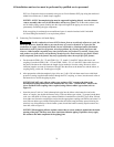
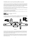
NOTICE: For models CDB1-100 and CDB1-125 used in horizontal applications, immediately
transition from 2-inch to 3-inch diameter pipe by installing the 3-inch x 2-inch diameter PVC reducer
just outside the furnace casing. The remainder of the venting system leading away from the furnace
must be composed of 3-inch diameter PVC pipe and pipefittings only. Refer to item E in Figure 8.
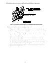
b. After preparation of the internal 2-inch diameter PVC pipe sections, put a thin bead of a silicone rubber
type sealant around the outlet flange of the inducer. Slip the 2-inch diameter PVC elbow (for the model
series CDB1 in horizontal applications, a 2-inch diameter PVC tee) over the inducer outlet flange.
Drive one (1) #8 x 3/4 inch sheet metal screw with black protective coating (supplied with furnace)
through the elbow and into the outlet flange of the inducer to secure the elbow in place.
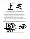
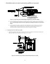
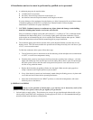
Figure 9: Typical Internal
Vent Piping Arrangement for
the Furnace Model Series
CHB1.
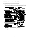
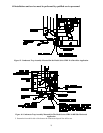
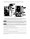
Figure 10: Typical Internal
Vent Piping Arrangement for
the Furnace Model Series
CDB1-100 / -125.
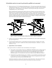
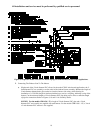
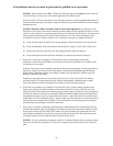
Figure 11: Typical Internal
Vent Piping Arrangement for
the Furnace Model Series
CDB1-100 / -125 in RH
Horizontal Applications.
c. Using PVC cement, glue the pre-cut 2-inch diameter thermoplastic pipe, from step (a) above, to the 2-
inch diameter PVC elbow (for the model series CDB1 in horizontal applications, the 2-inch diameter