


5
www.thermastor.com • sales@thermastor.comToll-Free 1-800-533-7533
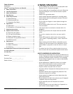
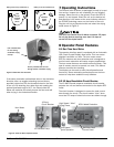
Figure 7: Birds eye view of room set-up
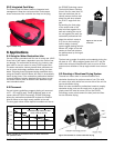
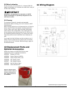
GFCI: Added Protection
High Speed: “Ultra”
Drying Power
Low Speed:
Quiet Operation
12 Amp
Circuit Breaker
AC Indicator Lamp
Stainless Steel
Control Panel
Hour Meter
Figure 9: Axial Air Mover Operator Panel
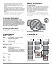
If the water restoration professional dries in the clockwise
direction often, we suggest attaching the two (factory
provided) rubber feet into the threaded holes on the side
of the unit. By attaching the rubber feet and creating the
optimal downward angle of 4.5°, the Phoenix Axial Air
Mover will maximize air velocity across the floor and wall
when drying in the clockwise direction.
7 Operating Instructions
The Phoenix Axial Air Mover as packaged is ready to be put
into service. Inspect the unit completely for any shipping
damage. Place the unit on the ground. Check the GFCI to
ensure it is not tripped. Orient the unit so the desired air
flow direction is the same as the arrow indicator sticker in
the FOCUS Technology corner on the interior of the unit.
Plug the unit into a grounded outlet and select the drying
mode shown in Figure 9.
CAUTION: The Phoenix Axial Air Mover consumes 2.5 Amps.
Do not plug devices requiring more than 9.0 Amps of
current into the duplex outlet.
8 Operator Panel Features
8.1 Run-Time Hour Meter
The operator interface panel is equipped with an Automatic
LCD (Liquid Crystal Display) Hour meter. This hour meter
displays cumulative run time. The hour meter meets
IP65 for moisture and dust protection and is designed to
survive harsh restoration and water recovery applications.
The hour meter features non-volatile eeProm memory. This
type of memory cannot be erased, nor reset. This feature
ensures accurate time tracking.
The display can be used to track time-of-operation and
time-to-dry. Some restoration professionals use the hour
meters to help them establish hourly billables.
8.2 12 Amp Resettable Circuit Breaker
The 12 AMP thermal response resettable circuit breaker
protects the unit and devices connected to its duplex GFCI
outlet.
The circuit breaker is designed to sense the total current
draw through the circuit. The circuit breaker “trips” when
more than 12 amps of electrical current are drawn through
Counter
clockwise
airflow
pattern
Clockwise
airflow
pattern
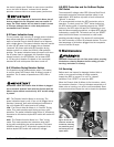
Making use of factory installed feet (4) Making use of user installed feet (2)
Figure 8: Clockwise feet locations
User installed feet
for use during
clockwise drying
set-ups
Factory installed feet for use
during counter clockwise drying