


8
www.thermastor.com • sales@thermastor.comToll-Free 1-800-533-7533
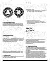
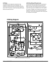
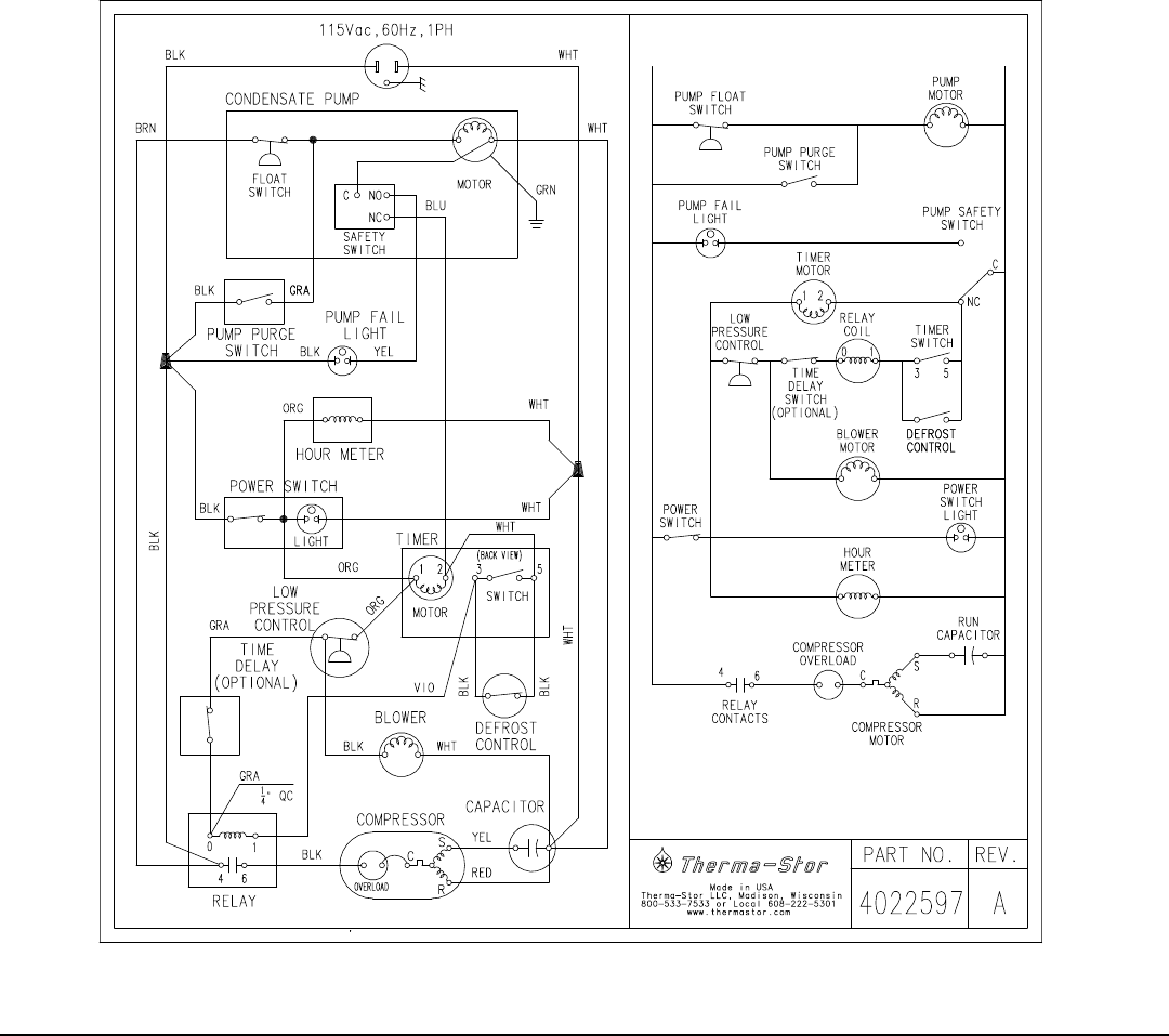
Figure 3: Electrical schematic of Phoenix 300
5 Wiring Diagram
4.9 Relay
The contacts of the single pole, single throw relay
complete the power circuit to the compressor. The
contacts are closed when power is provided to the relay
coil via the control circuit. The control circuit includes the
power switch, low pressure control, time delay (HP model),
defrost thermostat and timer.
4.10 Time Delay (HP model only)
The HP model has a time delay relay in the compressor
control circuit. This relay delays the compressor start
about 2 minutes after the power switch is turned on.
This reduces the unit’s starting amp draw by starting the
blower and compressor at different times. This reduces
the chance of tripping a circuit breaker during hard start
situations, such as when the unit has been stored in a
cold place. It also reduces compressor short cycling after
the compressor has stopped.