


3
www.thermastor.com • sales@thermastor.comToll-Free 1-800-533-7533
2.3 Electrical Requirements
The Phoenix 300 can be plugged into a grounded 15 Amp
circuit. At 80°F, 60% RH, it draws 11.e Amps. Due to the
high percentage of a 15 Amp circuit’s capacity that the
unit uses, the circuit should be dedicated to running it
only. Amp draw decreases at lower loads and increases
at higher loads. At extremely high loads, a 20 Amp circuit
may be required.
The unit briefly draws more amps to start if it has been
stored in a cold area. This may cause a 15 Amp circuit
breaker to trip. A 20 Amp circuit is recommended in such
situations. Some models have a time delay to delay the
compressor start about 2 minutes after the power switch
is turned on. This reduces the unit’s starting amp draw by
starting the blower and compressor at different times.
If an extension cord is required, it must have a minimum of
12 gauge conductors if 25 feet long or less and 10 gauge
conductors if greater than 25 feet long.
2.4 Condensate Removal
The Phoenix 300 is equipped with an internal condensate
pump to remove the water that is condensed during
dehumidification. This allows the condensate to be
pumped 30’ with the attached hose. If the condensate
must be pumped more than 20 feet above the unit, a
second pump must be added to relay the condensate.
2.5 Ducting
A detachable 10” round exhaust collar is supplied that
will allow a 10” round flexible duct to be attached to the
Phoenix 300 outlet. The duct and collar may be quickly
attached to the Phoenix 300 by sliding the 4 collar tabs
into the slots around the blower outlet and rotating the
collar clockwise. It may be quickly removed to transport
the unit more easily.
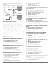
2.6 Power Switch
The power switch (on left side of hour meter) lights up
when the unit is turned on. The unit will continue to run
in all conditions until the switch is turned off; there is no
dehumidistat.
2.7 Pump Purge Switch
This switch (on right side of hour meter) minimizes the
water left in the condensate pump reservoir for moving or
storage. Pressing and holding the pump purge switch will
cause the condensate pump to run. Hold the switch in
until the flow from the condensate hose stops.
2.8 Pump Fail Light
If the condensate pump fails, water draining into the pump
reservoir will fill above its normal level. A safety float
switch will then turn on the pump fail light (located next
to the pump purge switch) and stop the compressor. This
prevents water from overflowing and wetting the floor. The
safety switch will not allow the compressor to restart until
water has been removed from the pump reservoir.
2.9 Hour Meter
The digital hour meter measures the cumulative time that
the unit is turned on to tenths of an hour. It stores its
total when the unit is unplugged; the previous total will be
displayed when the unit is next turned on. It resets to zero
after 99,999.9 hours of operation.
2.10 Defrost Control Adjustment
When the Phoenix 300 is used in a cool area, frost will
form on the cooling coil as it dehumidifies. When enough
frost forms, the defrost thermostat will initiate the
timed defrost cycle. The cycle periodically turns off the
compressor while allowing the blower to run. The frost is
melted by the air that the blower draws through the cooling
coil.
The defrost cycle is automatic and designed for optimum
performance above 50°F. If the unit is used in an area that
is below 50°F for more than 2 hours, adjustment of the
defrost timer is recommended to improve performance
(see Sec. 2.10).
DRYING TIP: Air’s ability to absorb moisture from wet
surroundings and the Phoenix 300’s ability to remove
moisture from that air is greatly improved at higher
temperatures. We recommend that the area to be dried be
heated to over 70°F if possible. Less drying time will be
required and efficiency will improve.
To adjust the defrost timer:
1. Unplug the unit.
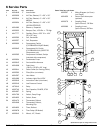
2. Remove the front cover (6 screws).
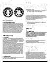
3. The timer is fastened to the right inside panel. Every
fourth peg around the dial is pushed out from the dial
center except one section with 5 pegs out in a row.
See figure 1. Each fourth “out” peg represents 15
minutes of compressor “off” time during every hour
that the unit is in the defrost cycle.
4. To improve performance below 50°F, the compressor
“off” time must be increased to 30 minutes per hour
to allow the frost to completely melt. To do this, push
the pegs out from the dial center so that the pegs
alternate with 2 toward the center, then 2 out from
the center, all the way around the dial except for the
section now with 6 pegs out in a row (see Fig. 1).