


8. Ver ify re cep tion. With the trans mit ter and re ceiver on and
match ing Group and Chan nel, the main re ceiver dis play
should be in di cat ing a RF sig nal on the bar graph. Speak
into the mi cro phone and the Au dio Me ter bar graph should
in di cate au dio sig nal pres ence. If the level me ters do not
show re cep tion, make sure the chan nels are match ing and
re fer to the trou ble shoot ing sec tion.
9. Ad just ment of the trans mit ter au dio gain - If nec es sary
The trans mit ter au dio gain is fac tory set at the mid dle of
the range, which should be suit able for most ap pli ca tions.
For loud or soft speak ers/sing ers, a gain ad just ment may
be nec es sary. Have the speaker or singer use the mi cro --
phone in a nor mal per for mance level voice. The Au dio
Me ter in the main re ceiver dis play screen should show
peaks around the -3dB level. If the me ter peaks all the way
to the right or well be low the -3dB level, ad just the trans --
mit ter au dio gain.
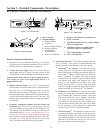
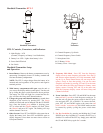
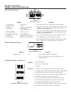
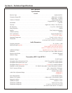
Bodypack Trans mit ter - BPU-2
Fig ure 5
Bodypack Trans mit ter
BPU-2 Con trols, Con nec tors, and In di ca tors
To ad just the trans mit ter gain, gently in sert the pro vided
screw driver (or other 3/32 - 2.5 mm screw driver) into the
ad just ment hole op po site the dis play screen. Turn lightly
un til the screw driver tip goes into the ad just ment level
con trol. Gently turn coun ter clock wise un til the con trol
stops (the mi cro phone out put is at min i mum but not off).
Slowly turn the gain con trol up (clock wise) while speak --
ing/sing ing into the mi cro phone and the au dio me ter
shows peaks around -3 dB.
NOTE: Op er at ing with the trans mit ter au dio gain set as
high as pos si ble (with out dis tor tion or peaks all the way to
the right end of the me ter) will re sult in the best per for --
mance and high est sig nal to noise ra tio.
10. Test Per for mance. Go back to Sec tion 3. Re ceiver Setup
and Op er a tion - Step 9 to com plete sys tem set up and test.
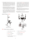
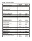
Fig ure 6
Con trol View
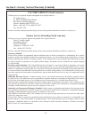
Fig ure 7
Top View
-5-
SETSET
6
9
5
OFFOFF
ON ON
BATTBATT
4
2
3
755050755050
GPGP CHCH
1
8
5
755050755050
GPGP CHCH
RR
1.
An tenna - flex i ble 1/4 wave an tenna
2.
Power On/Off Switch
3.
Bat tery Low LED In di ca tor
4.
TA4 Au dio Con nec tor
5.
LCD Dis play (Chan nel, Fre quency or
Bat tery Level Indication)
6.
Dis play Con trol But tons (Set/Up/Down)
7.
Belt Clip (Re mov able, not shown)
8.
9V Bat tery Compartment
9.
Au dio Gain Adjustment