


2. Installation Power Connections
16
PDRP-1002 Instruction Manual PN 51135:B0 04/06/01
Power Connections
WARNING: Do not apply any type power to this control panel until all connections have been
made and verified.
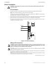
AC Connections
Disconnect (open) the circuit breaker in the AC main breaker panel and tag it “Out of Service”.
Note: Refer to "Power-Up Procedure" on page 31 before closing AC breaker.
Primary power required for the PDRP-1002 control panel is 110/120 VAC, 50/60 Hz, 1.2 amps and for
the PDRP-1002E is 220/240 VAC, 50/60 Hz, 0.6 amps.
Overcurrent protection for this circuit must comply with Article 760 of the National Electrical Code (NEC)
and/or local codes. Use #14 AWG (2.00 mm
2
) or larger wire with 600V insulation rating.
A separately fused and protected power connection to the panel should be supplied to prevent voltage
fluctuation and interruption of power.
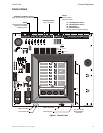
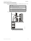
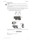
Figure 4 AC Power Connections
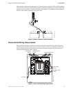
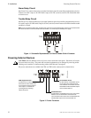
Battery (DC) Connections
WARNING: Battery contains sulfuric acid which can cause severe burns to the skin and eyes and
can destroy fabrics. If contact is made with sulfuric acid, immediately flush the skin or eyes with
water for 15 minutes and seek immediate medical attention.
CAUTION: Do NOT connect the battery interconnect wire at this time. Make this connection AFTER
initial system primary power connection.
Place batteries into bottom of cabinet as shown below. See "Appendix A: Secondary Power Calculations"
on page 39 for calculation of correct battery rating.
Note: Batteries are shipped separately and should be mounted only after the cabinet has been installed, the conduit
connected, and all wiring pulled, tested, and made ready to be terminated.
Continued on the next page...
!
J3
J9
J2
AMP
TB5
MS44-ACconn.cdr
Ground
Neutral
Hot
!
!