


NOTE: DIAGRAMS & ILLUSTRATION NOT TO SCALE.
9
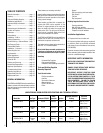
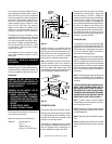
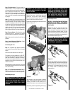
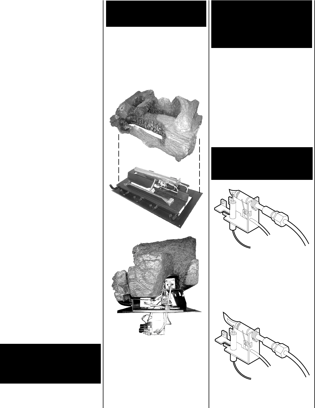
Figure 17
After setting the logs into position as shown
above, ensure they are properly and firmly
situated. The heater will not function as in-
tended if the logs are not correctly positioned.
Periodically check the positioning of the logs.
WARNING: FAILURE TO POSITION THE
PARTS IN ACCORDANCE WITH THESE
DIAGRAMS OR FAILURE TO USE ONLY
PARTS SPECIFICALLY APPROVED WITH
THIS HEATER MAY RESULT IN PROP-
ERTY DAMAGE OR PERSONAL INJURY.
Step 13. The heater includes a unitized set of
ceramic fiber logs. Handle these logs with
great care. The logs can be easily damaged,
but when handled properly they can provide
years of performance and enjoyment.
Position the unitized log set unto the burner as
shown in
Figure 17
.
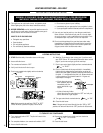
Flame Appearance
REFER TO THE OPERATING INSTRUCTIONS
LOCATED AT THE BACK OF THIS MANUAL
BEFORE LIGHTING THE HEATER TO OBSERVE
THE FLAMES.
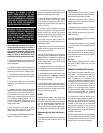
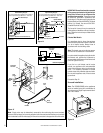
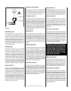
Flames from the pilot, front and rear burner
should be visually checked as soon as the
heater is installed. In addition a periodic visual
check of the flames should be made. The pilot
flame should always be present when the heater
is in operation and should just envelope the tip
of the thermocouple (
Figure 18
).
WARNING: NO ADJUSTMENTS ARE TO
BE MADE TO THE ODS PILOT SYSTEM.
TAMPERING WITH THIS SYSTEM CAN
BE EXTREMELY HAZARDOUS.
Figure 18
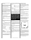
An incorrect pilot flame is shown in
Figure 19
.
This pilot flame will cause the thermocouple to
cool. When the thermocouple cools, the heater
will shut off. If pilot flame pattern is incorrect,
or if heater shuts off, contact your service
representative.
Figure 19
WARNING: DO NOT PLACE ANY LAVA
ROCK ON LOGS OR BURNERS. THIS MAY
CAUSE SOOTING.
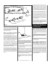
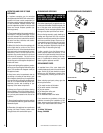
Connecting Gas Line
Step 11. A qualified gas appliance installer
must connect the gas room heater to the gas
supply.
Consult all local codes and refer to Step 5.
The heater gas inlet connection is 3/8" NPT,
located on the left side facing the heater. If a
right side connection is required, the connec-
tion pipe may be piped under the rear of the
appliance to end at the left hand side for con-
nection to the inlet.
When tightening up the joint to the valve hold
the valve securely with a wrench to prevent the
valve from moving.
Step 12. For Surround Installations Only –
Finish the assembly of the surround compo-
nents and secure the surround to the appliance.
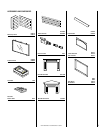
Assembling the Logs
WARNING: DO NOT ADD EXTRA LOGS
OR ORNAMENTS SUCH AS PINE CONES,
VERMICULITE OR ROCK WOOL. USING
THESE ADDED ITEMS CAN CAUSE
SOOTING.
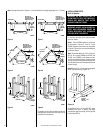
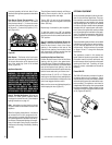
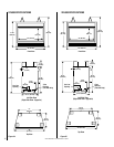
Step 8. Position Heater – Place the heater in
desired location. It may be helpful to tempo-
rarily assemble the surround around the appli-
ance to properly locate the unit. Refer to
Figure 16
for floor and platform installations.
If the heater is to be installed into a framed wall
refer to the built-in assembly steps beginning
on page 4.
Note: The heater may be installed directly on a
floor made of standard combustible wood con-
struction materials. Do not install the heater
directly on carpeting or other soft floor cover-
ing such as vinyl tile or flooring materials. Use
a wood or metal panel that extends the full
width and depth of the heater between the
heater and any soft floor covering material.
Refer to Figures 26 and 27 for base dimensions.
Step 9. Secure Heater – Bend the tabs down
(
Figures 2 and 15
). Using two (2) screws
securely tighten the appliance to the platform.
Note: Heater must be anchored to the floor or
platform.
Step 10. Install Optional 120V Wiring – Refer
to Step 5 for wiring instructions.