


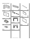
NOTE: DIAGRAMS & ILLUSTRATION NOT TO SCALE.
6
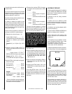
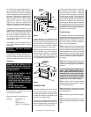
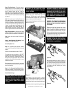
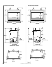
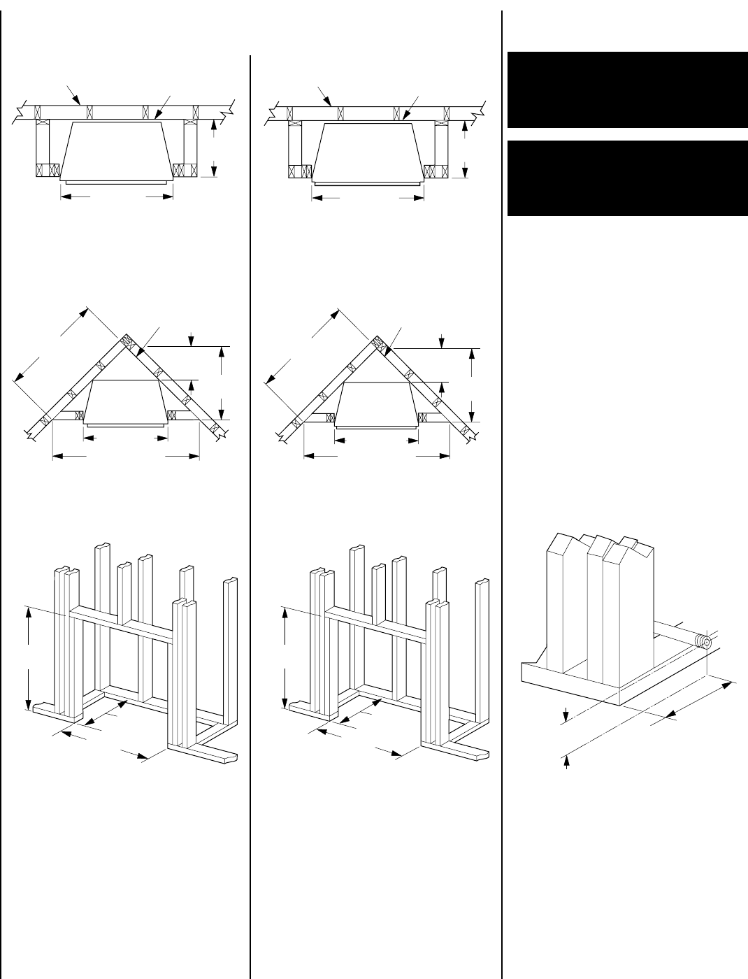
Note: Framing dimensions in Figures 4 - 9 are calculated for a nailing flange depth of
¹⁄₂
" (13 mm).
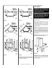
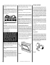
Figure 4
Figure 5
Figure 6
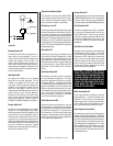
Figure 7
Figure 8
Figure 9
The header may be in direct contact with the top
metal spacers, but must not rest on them or be
notched to fit around them.
37" (940mm)
15 1/2"
(394mm)
Outside Wall
VF5000
Back Wall of
Chase/Enclosure
Including Finishing
Materials If Any.
37" (940mm)
58" (1473mm)
13 1/2"
(343mm)
29"
(737mm)
41"
(1041mm)
VF5000
Back Wall of
Chase/Enclosure
Including Finishing
Materials If Any.
37 1/4"
(946 mm)
37"
(940 mm)
15 1/2"
(394 mm)
VF5000
Back Wall of
Chase/Enclosure
Including Finishing
Materials If Any.
41" (1041mm)
19 1/2"
(495mm)
Outside Wall
VF6000
41" (1041mm)
67 3/4" (1721mm)
14 1/4"
(362mm)
33 7/8"
(860mm)
47 7/8"
(1216mm)
Back Wall of
Chase/Enclosure
Including Finishing
Materials If Any.
VF6000
42 3/8"
(1076 mm)
41"
(1041 mm)
19 1/2"
(495 mm)
VF6000
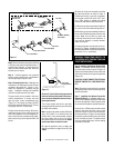
INSTALLATION STEPS
Built-In Systems
WARNING: DO NOT ALLOW FANS TO
BLOW DIRECTLY INTO THE FIREPLACE.
AVOID ANY DRAFTS THAT ALTER
BURNER FLAME PATTERNS.
WARNING: DO NOT USE A BLOWER IN-
SERT, HEAT EXCHANGER INSERT OR
OTHER ACCESSORY NOT APPROVED
FOR USE WITH THIS HEATER.
Do not burn solid fuels in this listed unvented
gas room heater.
Step 1. Frame VF5000 appliance enclosures
as illustrated in
Figures 4, 5 and 6
. Frame
VF6000 appliance enclousures as illustrated
in
Figures 7, 8 and 9
for surround installations
proceed to Step 8.
Note: The framed depth (15-1/2" for a flat wall,
29-1/4" for a corner VF5000 and 22-5/8" and
36-3/8" for a VF6000 ) must always be mea-
sured from a finished surface. If a wall covering
such as drywall is to be attached to the rear wall,
then the dimension must be measured from the
drywall surface.
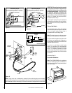
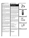
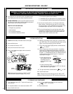
Step 2. Route a 1/2" (13 mm) gas line along the
left or right side framing (
Figure 10
).
Figure 10
All appliances have a 3" long 3/8" NPT nipple
installed at the valve. To quickly and easily
complete the gas line routing, use the gas flex
line kit, Model GFLV.
3"
(76 mm)
VF6000 - 11"
(279 mm)
VF5000 - 7 1/2"
(191 mm)