


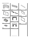
NOTE: DIAGRAMS & ILLUSTRATION NOT TO SCALE.
7
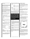
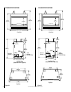
Figure 11
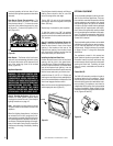
Control
Valve
Lower Control
Compartment Door
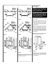
Step 3. Ensure the hood is properly positioned
in the open area above the appliance door. If
required insert the tabs, on each end of the
hood, into the bracket at each end. Bend the
two tabs over to secure.
Step 4. Position appliance into prepared
framing, secure with 6d nails or equivalent at
the nailing flange along each side.
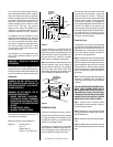
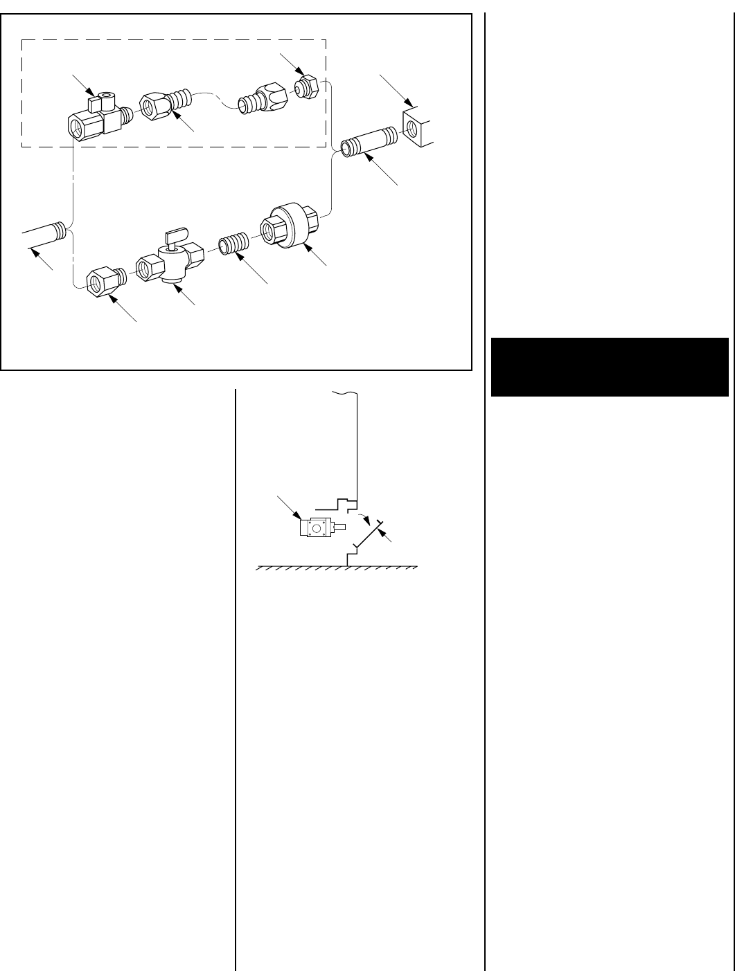
Step 5. Connecting Gas Line – Make gas line
connections. All codes require a shut-off valve
mounted in the supply line.
Figure 11
illus-
trates two methods for connecting the gas
supply. Installation methods and materials
must be in compliance with local codes.
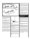
The gas control valve is located in the lower
control compartment. To access the valve
open the lower control compartment door
(
Figure 12
). The control valve has a 3/8" NPT
thread inlet port and is fitted with a 3" (76 mm)
long nipple, 3/8" NPT on both ends.
Plan the connections accordingly. We recom-
mend that the gas line be routed for the left
side of the appliance to ensure adequate ac-
cess to the rear lower compartment for instal-
lation and servicing of the optional FAB-1100
blower.
An external regulator must be used on all pro-
pane (L.P.G.) heaters, in addition to the regula-
tor fitted to the heater, to reduce the supply tank
pressure to 13" w.c. (maximum).
WARNING: CONNECTING DIRECTLY TO
AN UNREGULATED PROPANE TANK CAN
CAUSE AN EXPLOSION.
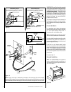
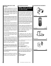
Step 6. Installing the Optional Remote Wall
Switch – The standard millivolt system comes
from the factory wired as shown in
Figure 13
.
Select a convenient location for the remote wall
switch and connect the wiring to the appliance
(
Figure 14
).
CAUTION: DO NOT CONNECT THE OPTIONAL
REMOTE SWITCH TO A 120V POWER SUP-
PLY.
Note: The optional rocker switch is mounted to
the appliance and wired in the same way as the
remote wall switch.
Step 7. Installing the Optional Forced Air
Blower Kit Wiring – A receptacle plate is pro-
vided for the installation of the FAB-1100 forced
air blower kit (optional). Electrical power must
be provided to this plate to operate the blower.
Route a 3-wire, 120Vac power line with control
switch to the lower left front corner of the
appliance. Supply wires are to be connected to
the outlet as shown in
Figure 15
, ensuring that
the polarity (as determined by the colors of the
wires) is exactly as shown. The black and red
wire loop must be left intact, with the mating
connectors connected.
Secure all joints tightly using appropriate
tools and sealing compounds (ensure pro-
pane resistant compounds are used in pro-
pane applications).
Turn on gas supply and test for gas leaks,
using a gas leak test solution (also referred to
as bubble leak solution).
Note: Using a soapy water solution (50% dish
soap, 50% water) is an effective leak test
solution but it is not recommended, because
the soap residue that is left on the pipes/
fittings can result in corrosion over time. Never
use an open flame to check for leaks.
A. Light the appliance (refer to safety and
lighting instructions on pages 18 and 19) (
See
*Note
).
Figure 12
B. Brush all joints and connections with the
gas leak test solution to check for leaks. If
bubbles are formed, or gas odor is detected,
turn the gas control knob to the “OFF” posi-
tion. Either tighten or refasten the leaking
connection and retest as described above.
C. When the gas lines are tested and leak free,
be sure to rinse off the leak testing solution.
D. When the gas lines are tested and leak free,
observe the individual tongues of flame on the
burner. Make sure all ports are open and
producing flame evenly across the burner. If
any ports are blocked, or partially blocked,
clean out the ports.
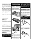
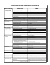
Gas Stub
1/2" x 3/8" Flare
Shut-Off Valve
3/8" Flex Tubing
3/8" NPT x 3/8"
Flare Fitting
3/8" Nipple, Standard
with all Units
3/8" Union
3/8" Close Nipple
3/8" Shut-Off Valve
1/2" x 3/8" Reducer
Gas Valve
Gas Flex Line Kit, Model GFLV