


8
NOTE: DIAGRAMS & ILLUSTRATIONS NOT TO SCALE.
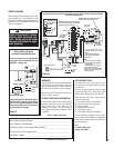
WARNING
The size and position of the log set
was engineered to give the appli-
ance a safe, reliable and attrac-
tive fl ame pattern. Any attempt
to use a different log set in the
fi replace will void the warranty
and will result in incomplete
combustion, sooting, and poor
fl ame quality.
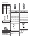
REFERENCE
Firebox Accessories / Parts
Cat. No. Model No. Description
88L53 FGE Bag of Glowing Embers
(1 oz. rockwool)
80L42 FDVS
Bag of Decorative
Volcanic Stone
Table 8
Bag of Glowing
Embers (rockwool)
Separate into Quarter
Size (separate) Pieces
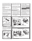
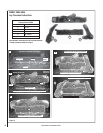
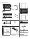
SSDV-4035 - Install as Follows
Carefully position the ceramic fi ber logs into the
fi rebox as shown in Figure 9. Logs should be
placed in the order shown and per the following
instructions.
1. Place embers on the front burner tube and
volcanic stone in front of the burner as
shown and per instructions on this Page
(see Placement of Glowing Embers & Install
Decorative Volcanic Stone on this page).
2. Place the rear log (A) as shown. Position
the 2 notches on the bottom of the log over
the 2 corresponding locating brackets as
shown.
3. Place the center log (C) as shown. The 2
notches on the bottom of the log should fi t
over the corresponding locating brackets.
4. Place the top right log (D) as shown. The top
fork on log (D) fi ts into notch on log (A) as
shown. The bottom fork on log (D) rests on
subfl oor fl ange (identifi ed in photo #1).
5. Place the top left log (B) as shown. The top
fork on log (B) fi ts into notch on log (A). The
bottom of the log rests on the subfl oor.
WARNING
DO NOT attempt to install the logs
until the appliance installation
has been completed, the gas line
connected and tested for leaks
and the initial burner operation
has been checked out.
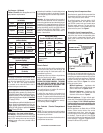
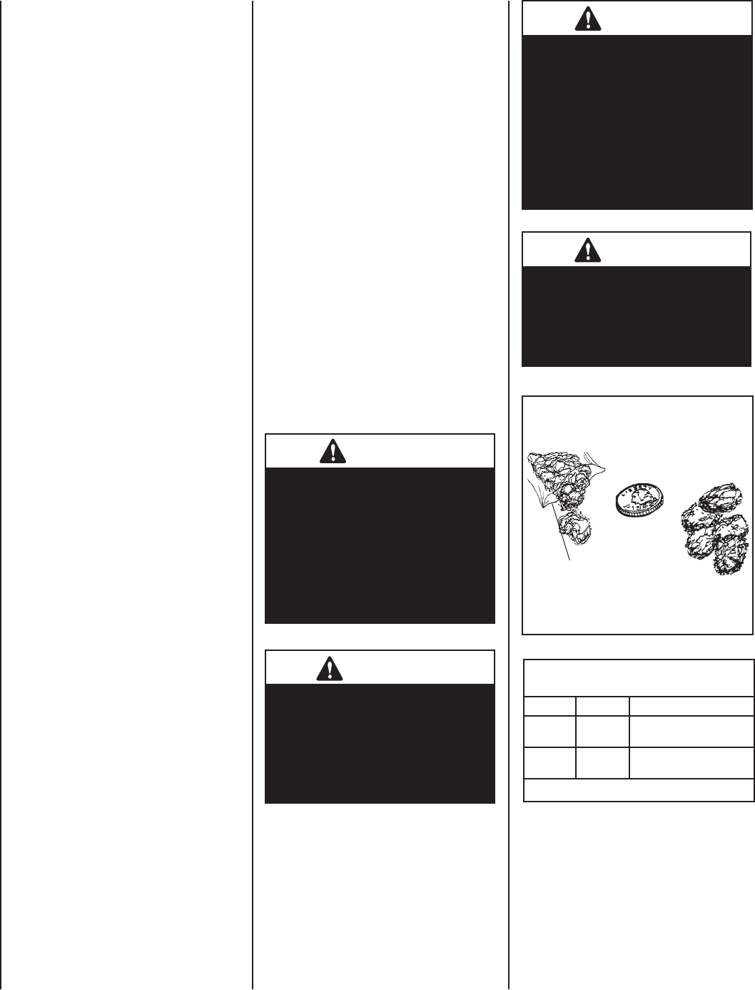
Figure 7 - Glowing Embers
WARNING
This appliance is not designed
to burn wood. Any attempt to
do so could cause irreparable
damage to appliance and prove
hazardous to your safety.
WARNING
If logs are not installed according
to the log installation instruc-
tions, fl ame impingement and
improper combustion could
occur and result in soot and/or
excessive production of carbon
monoxide (CO), a colorless,
odorless, toxic gas.
INSTALL VOLCANIC STONE, GLOWING
EMBERS AND LOGS
1. Remove front glass enclosure panel (see Re-
moving Glass Enclosure Panels on this page).
2. Carefully remove log set box from fi rebox.
Next, remove embers and volcanic stone
from the control compartment. Handle logs
carefully to prevent breakage.
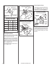
3. Install Decorative Volcanic Stone - Mound
up a portion of the volcanic stone in front of
the burner in a pleasing pattern.
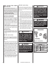
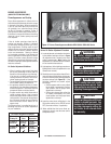
4. Placement of Glowing Embers -
Separate the Embers (rockwool) into pieces
about the size of a quarter (see Figure 7).
Keep the pieces fl uffed up, not matted.
Distribute these pieces over the surface of
the burner, as shown in Figures8 or 9. Do
not use more than is necessary. Ensure that
the main burner ports remain uncovered by
the ember material.
Note: This appliance is provided with enough
Glowing Embers for several applications, do
not use all that is in a new bag at one time.
For best glowing effect, replace the ember
material annually.
5. Placement of Logs -
The logs have locating notches or slots to
help ensure that they are properly positioned.
Proper log placement is critical to prevent
sooting.
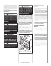
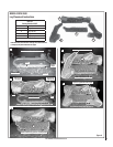
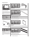
SSDV-3530 - Install as Follows
Carefully position the ceramic fi ber logs into the
fi rebox as shown in Figure 8. Logs should be
placed in the order shown and per the following
instructions.
1. Place embers on the front burner tube and
volcanic stone in front of the burner as
shown and per instructions on this Page
(see Placement of Glowing Embers & Install
Decorative Volcanic Stone on this Page).
2. Place the rear log (A) as shown. Position the
2 notches on the bottom of log (A) over the 2
corresponding locating brackets as shown.
3. Place the center log (C) as shown. The 2
notches on the bottom of log (C) fi t over
the corresponding locating brackets.
4. Place the left log (B) as shown. The top fork
on log (B) fi ts into the notch on log (A). The
bottom of log (B) rests on the subfl oor.
5. Place the top right log (D) as shown. The top
fork on log (D) fi ts into notch on log (A) as
shown. The bottom fork on log (D) rests on
subfl oor fl ange (identifi ed in photo #1).