


12
NOTE: DIAGRAMS & ILLUSTRATIONS NOT TO SCALE.
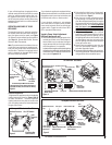
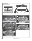
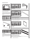
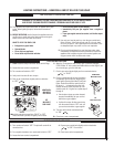
Figure 11
Burner Air Shutter Adjustment
Adjustment Rod Up
(Fully Open Position)
Air Shutter
Adjustment Rod Down
(minimum air opening
position)
Burner Tube
Adjustment Setscrew
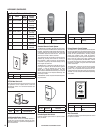
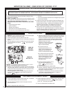
Electronic Appliance Checkout
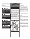
To light the burner, refer to the lighting instruc-
tions on Pages 19 & 20. Ensure the igniter
lights the pilot. The pilot fl ame should engulf
the fl ame sensor as shown in Figure 14.
With proper care and maintenance, your appli-
ance will provide many years of enjoyment. If
you should experience any problem, fi rst refer
to the troubleshooting guide in this manual.
If problem persists, contact your Lennox
distributor.
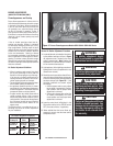
Figure 14
3/8" to 1/2"
(9 -13 mm)
Ground
Electrode
Flame Rod
Hot Surface
Igniter
Proper Flame
Adjustment
Pilot
Nozzels
ELECTRONIC PILOT ASSEMBLY
Proper Pilot Flame Appearance
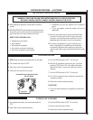
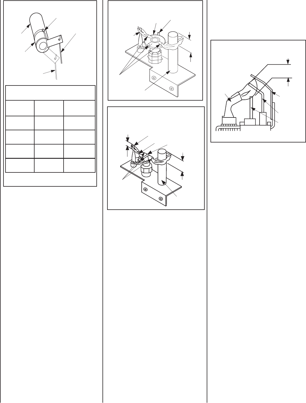
Figure 12
Thermocouple
Thermopile
Pilot
Nozzels
SIT MILLIVOLT PILOT ASSEMBLY
3/8" Min.
(9 mm)
Igniter Rod
Hood
Proper Pilot Flame Appearance
Figure 13
Proper Pilot Flame Appearance
Thermocouple
Thermopile
Pilot
Nozzels
3/8" Min.
(9 mm)
1/8" Min.
(3 mm)
Igniter Rod
Hood
HONEYWELL MILLIVOLT PILOT ASSEMBLY
Millivolt Appliance Checkout
The pilot fl ame should be steady, not lifting
or fl oating. Flame should be blue in color with
traces of orange at the outer edge.
The top 3/8" (10 mm) at the pilot generator
(thermopile) and the top 1/8" minimum (tip)
of the quick drop out thermocouple should be
engulfed in the pilot fl ame. The fl ame should
project 1" (25 mm) beyond the hood at all three
ports. See Figure 12 or 13.
To light the burner, refer to the lighting instruc-
tions on Pages 17 & 18.
Main Burner Factory Air Shutter
Opening Setting - Inches (millimeter)
Model Natural
Gas
Propane
Gas
SSDVT-3530
1/4
(6.35 mm)
1/2
(12.70 mm)
SSDVR-3530
1/4
(6.35 mm)
1/2
(12.70 mm)
SSDVT-4035
1/4
(6.35 mm)
1/2
(12.70 mm)
SSDVR-4035
1/4
(6.35 mm)
1/2
(12.70 mm)
Ref. Air shutter Patent:
U.S. Pat. 5,553,603