


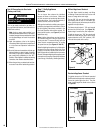

pull the switch/bracket assembly (with
low voltage wires attached) through the
side panel slot into the rebox.
8 - Replace the switch, if necessary..
9 - Reinstall the scoop and lintel.
10 - Reinstall the glass enclosure panel and
control compartment access panel.
The appliance should then relight and remain
lit. If this does not occur, contact your dealer.
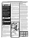
Step 11. Perform Spillage Test
After appliance installation, perform this spillage
test to verify proper venting conditions:
1 - Place unit in its normally-operated condi-
tion, that is, with the glass enclosure panel
in place.
2 - Close all doors and windows in the room.
Turn on all exhaust fans in the house.
3 - Light the appliance.
4 - Wait 15 minutes.
5 - To check for venting action, start by hold-
ing a smoke producing device below the
glass enclosure panel. The smoke should
be drawn into the control compartment.
Continue the test by moving the smoke-
producing device along the entire length
of the lower edge of the glass enclosure
panel.
6 - If the smoke is NOT drawn into the con-
trol compartment, turn off the appliance
and call a qualified service technican.
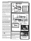
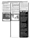
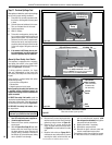
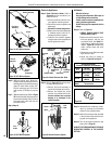
Manually-Reset Safety Limit Switch
This appliance is equipped with a manually-
reset safety limit switch in the upper RIGHT
side of the rebox, behind the right side scoop.
Refer to Figure 29 for its location.
If, during appliance operation, the flame
goes out (independently of the burner ON/
OFF switch), the safety limit switch may have
tripped.
Some causes for a tripped safety limit switch
include the following:
• Incorrect flue configuration
• Blocked flue
• Negative pressure inside house
Before resetting the safety limit switch, have
a qualified service technician inspect the
fireplace and venting for these conditions and
repair as needed.
To RESET the safety limit switch, push the
reset button located between the wire terminals
on the back of the switch. Follow the steps be-
low to access the switch (also see Figure 29-C).
To REPLACE the safety limit switch, follow
the steps below.
IMPORTANT: This procedure should only be
performed by a qualified service technician.
1 - Turn OFF electrical power to appliance.
2 - Allow the appliance to cool.
3 - Remove the lower control compartment
access panel.
4 - Refer to Figure 25 on Page 20. Open both
latches under the rebox oor securing
the glass enclosure panel. Remove the
panel by tilting it outward at the bottom
and lifting it up. Set aside the panel, taking
care to protect it from damage.
5 - Remove the (3) screws securing the lintel,
and then remove the lintel. One of the lintel
cabinet top holes is shown in Figure 29.
6 - Remove the (3) screws securing the
scoop, and then remove the scoop. Refer
to Figure 29 for correct location for model
size.
7 - Reset the limit switch per Figure 29-B. If
unit does not reset, remove the (2) screws
securing the safety switch bracket, and
SUPERIOR
®
B-VENT GAS FIREPLACES • MODELS SLBV-35, SLBV-40 • INSTALLATION INSTRUCTIONS
22
NOTE: DIAGRAMS & ILLUSTRATIONS ARE NOT TO SCALE.
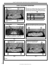
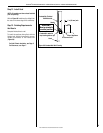
Safety Limit Switch / Reset Button Location
Inside View of Firebox (upper right side)
Figure 29
Figure 29-C
Limit Switch
Wire Terminals
(Red reset button
is between the
two terminals.)
Cabinet
Corner
Door
Frame
~
~
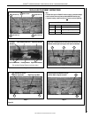
Figure 29-B
Figure 29-A
To access the Safety Limit Switch, reach in and up
behind the Bracket, and push the red reset button
located between the two Wire Terminals.
Upper Right Side of Firebox
(right side Scoop removed)
Lintel Screw Hole
in Cabinet Top
~
~
Bracket (right side Scoop removed)
Right Side
Scoop
3 Scoop Screws
Lintel Screw Hole
in Cabinet Top
Right Side
of Firebox