


SUPERIOR
®
B-VENT GAS FIREPLACES • MODELS SLBV-35, SLBV-40 • INSTALLATION INSTRUCTIONS
12
NOTE: DIAGRAMS & ILLUSTRATIONS ARE NOT TO SCALE.
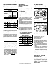
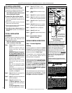
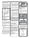
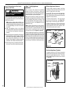
Step 4. Install Field Wiring
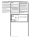
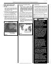
CAUTION
Ground supply lead must be con-
nected to the wire attached to the
green ground screw located on the
outlet box. See
Figure 13. Failure to
do so will result in a potential safety
hazard. The appliance must be
electrically grounded in accordance
with local codes or, in the absence of
local codes, the National Electrical
Code, ANSI/NFPA 70-latest edition.
(In Canada, the current CSA C22-1
Canadian Electrical Code).
CAUTION: Label all wires prior to disconnec-
tion when servicing controls. Wiring errors
can cause improper and dangerous operation.
ATTENTION : Au moment de l'entretien
des commandes, étiquetez tous les fils
avant de les débrancher. Des erreurs
de cáblage peuvent entraîner un fonc-
tionnement inadéquat et dangereux.
Verify proper operation after installing.
A. All Models
• An optional unit-mounted ON/OFF switch
may be installed in the lower control com-
partment.
• An optional wall-mounted ON/OFF switch or
optional ON/OFF remote control kit also may
be used.
• If a wall-mounted ON/OFF control switch is
used, mount it in a convenient location on a
wall near the fireplace.
• If an optional Style View Door is used in
conjunction with an optional unit-mounted
ON/OFF switch, the switch may be mounted
onto the Style View Door per instructions
provided in kit.
• The gas valve is set in place and pre-wired at
the factory on all models.
Refer to Section B (below) for millivolt appli-
ances and Section C (below) for electronic
appliances.
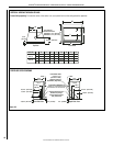
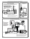
B. Millivolt Wiring (see Figure 12)
1. Read Section A, “All Models,” at left.
2. Wire the control switch within the millivolt
control circuit using the 15 feet of 2 conductor
wire supplied with the unit.
Note: The supplied 15 feet of 2 conductor
wire has one end of each conductor con-
nected to the gas valve circuit and the other
end of each conductor placed loose inside
the bottom compartment.
CAUTION: Do Not connect the optional wall
switch to a 120V power supply.
C. Electronic Wiring (see Figure 13)
Note: The electronic appliance must be con-
nected to the main power supply.
1. Read Section A, “All Models,” at left.
2. Route a 3-wire 120Vac 60Hz 1ph power
supply to the appliance junction box.
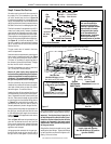
3. Remove the electrical inlet cover plate from
the side of the unit by removing the plate's
securing screws (see Figures 8-1 and 8-2
on Pages 9 and 10).
4. Remove the cover plate's knockout; then feed
the power supply wire through the knockout
opening and into the unit junction box.
5. Connect the black power supply wire to the
lower outlet's red pigtail lead and the white
power supply wire to the common terminal
of the outlet as shown in Figures 13 and 14.
6. Connect ground supply wire to pigtail lead
attached to outlet's green ground screw.
Note: Remote receiver should be located in the
wall, or if installed in the control compartment,
pulled all the way forward and completely to the
left or right against the corner posts. The glass
enclosure panel must be removed first to place
the receiver in the lower control compartment.
7. If using an optional control, wire it in the low
voltage circuit as shown in Figure 13.
Note: The supplied 15 feet of 2 conductor wire
has one end of each conductor connected
to the gas valve circuit and the other end
of each conductor placed loose inside the
bottom compartment.
8. After wiring is complete, replace cover plate.
Note: Do NOT install batteries in the battery
holder until needed (i.e., in the event of a
power outage or if operating the appliance
solely by batteries). The battery holder requires
two [2] "D" batteries.
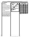
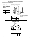
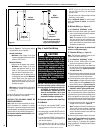
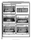
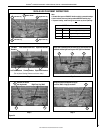
3. Refer to Figure 11. The following venting
congurations may be installed:
Vertical Installations
• Minimum overall height of the vent
system and appliance without an offset
must be 10 ft (2.54 m).
Offset Installations
• Offset up to 45 degrees from vertical:
Minimum overall height of the vent
system and appliance must be 12 ft
(3.66 m). The lower part of the offset
may start at the fireplace flue collar.
• Offset greater than 45 degrees and up
to 60 degrees from vertical: Minimum
overall height of the vent system and
appliance must be 15 ft (4.57 m). The
lower part of the offset may start at the
fireplace flue collar.
Maximum overall height of the vent system
and appliance should not exceed 40 ft
(12.19 m).
Install the B-vent system in accordance with
the vent manufacturer's instructions.
CAUTION: THIS APPLIANCE CANNOT BE
VENTED HORIZONTALLY.
Note: Refer to the vent manufacturers instal-
lation instructions for variations of venting
techniques. If common venting of several units
is contemplated, it should be discussed with an
architect and the local Building Department.
Do not place insulation materials within 1 in.
of the gas vent system.
Back View
Of Appliance
10 ft.
Minimum
Back View
Of Appliance
*12 ft. Min.
**15 ft. Min.
*with an offset up to 45 degrees
** with an offset greater than 45
degrees and up to 60 degrees
Vertical
Installations
Back View
Of Appliance
10 ft.
Minimum
Back View
Of Appliance
*12 ft. Min.
**15 ft. Min.
*with an offset up to 45 degrees
** with an offset greater than 45
degrees and up to 60 degrees
Offset
Installations
Figure 11