


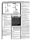

Note:
• All appliances are factory-equipped with
a exible gas line connector and 1/2 inch
shutoff valve (see Figure 17 on Page 15).
• See Massachusetts Requirements on Page
4 for additional requirements for installa-
tions in the state of Massachusetts in the
USA.
• The gas supply line should NOT be con-
nected to the appliance until Step 6 on Page
15).
• A pipe joint compound rated for gas should
be used on the threaded joints. Ensure that
propane-resistant compounds are used in
propane applications. Be very careful that
the pipe compound does not get inside the
pipe.
• It is recommended to install a sediment trap
in the supply line as close as possible to the
appliance. Appliances using propane should
have a sediment trap at the base of the tank.
• Check with local building ofcial for local
code requirements (e.g., whether below-
grade penetrations of the gas line are al-
lowed, etc.).
IMPORTANT: If propane is used, be aware that
if the tank size is too small (i.e., under 100 lbs
if this is the only gas appliance in the dwell-
ing; ref. NPFA 58), there may be pressure loss
resulting in insufficient fuel delivery, which
can result in sooting, severe delayed ignition,
or other malfunctions. Any damage resulting
from an improper installation, such as this, is
not covered under the limited warranty.
Proper Sizing of Gas Line
Properly size and route the gas supply line
from the supply regulator to the area where the
appliance is to be installed per requirements
outlined in the National Fuel Gas Code, NFPA
54 - latest edition (USA) or CAN/CSA-B149.1 -
latest edition (Canada).
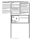
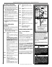
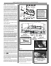
NOTE: Gas line can be routed to either
side. Reverse this illustration if routing
to right side.
Also see Figures 8-1 and 8-2.
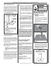
Figure 9: Route Gas Line
3"
(76 mm)
Left Side Front
Corner of Fireplace
Framing
6-1/2"
(152 mm)
Pipe Coupling
(Recommended)
Step 2. Route the Gas Line
Route a 1/2" (13 mm) gas line to either side
of the appliance (left side routing is shown
in Figure 9 ). Gas lines must be routed, con-
structed, and made of materials that are in strict
accordance with local codes and regulations.
All appliances are factory-equipped with a flex-
ible gas line connector and 1/2-inch shutoff
valve. (See Step 6 on Page 15.)
Never use galvanized or plastic pipe. Gas lines
must be routed, constructed and made of ma-
terials that are in strict accordance with local
codes and regulations.
IMPORTANT: It is critical that a licensed
installer perform this step strictly per
NFPA.
We recommend that a qualified, licensed
plumber or gas tter be hired to correctly size
and route the gas supply line to the appliance.
Installing a gas supply line from the fuel supply to
the appliance involves numerous considerations
of materials, protection, sizing, locations, con-
trols, pressure, sediment, and more. Certainly no
one unfamiliar and unqualified should attempt
sizing or installing gas piping.
SUPERIOR
®
B-VENT GAS FIREPLACES • MODELS SLBV-35, SLBV-40 • INSTALLATION INSTRUCTIONS
Step 3. Install Venting System
and Exterior Termination
These instructions should be used as a
guideline and do not supercede local codes
in any way.
Install venting according to local codes, these
instructions, the current National Fuel Gas
Code in the USA (ANSI-Z223.1) or the current
standards in Canada (CAN/CSA-B149.1).
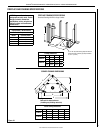
SLBV-35 and SLBV-40 series fireplaces must
be vertically vented using listed type-B,
double-walled vent pipe with the proper
diameter (as listed below) and a listed vent
termination.
Required Pipe Diameter
SLBV-35 series: Requires 4 in. (102 mm)
SLBV-40 series: Requires 5 in. (127 mm)
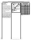
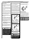
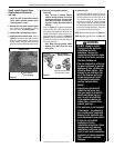
Figure 10b
Type B-Vent
SLBV-35 models: 4 in. (102 mm)
SLBV-40 models: 5 in. (127 mm)
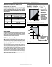
WARNING: EDGES OF SHEET METAL ARE
SHARP! WEAR PROTECTIVE GLOVES AND USE
EXTREME CARE WHEN HANDLING.
Required tools:
•SheetMetal-resistantGloves
•TinSnips
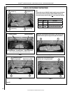
1. Using tin snips, cut the three connecting
points securing the slug to the three tabs
in the flue collar (as shown in Figure 10a),
and remove the slug.
Carefully dispose of slug in an appropriate
container.
2. Connect the proper size Type B-vent system
to the replace ue collar by bending up the
three tabs and securing with three sheet
metal screws (No. 8 or larger) bend up tabs.
See Figure 10b. Then install the remainder
of the Type B-vent to the outside.
Slug
11
NOTE: DIAGRAMS & ILLUSTRATIONS ARE NOT TO SCALE.
WARNING
Sharp Edges.
Watch Your Fingers!
Figure 10a
Cutting
points