


SUPERIOR
®
B-VENT GAS FIREPLACES • MODELS SLBV-35, SLBV-40 • INSTALLATION INSTRUCTIONS
Only doors certified with the appliance
shall be used.
Seules des portes certifiées pour cet
appareil doivent être utilisées.
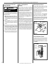
CAUTION: DO NOT abuse glass enclosure
panel by striking or slamming shut.
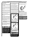
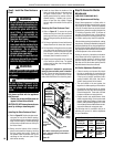
Installing the Glass Enclosure Panel
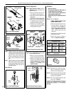
1. Refer to Figure 25. Position the glass enclo-
sure panel in front of the rebox opening,
with the bottom of the enclosure panel held
away from the fireplace. Hook the top flange
of the enclosure panel frame over the top of
the rebox frame.
2. Gently move the bottom of the enclosure
panel frame toward the replace, ensuring
that the gasket seats evenly. Fasten the
two latches under the rebox oor to the
vee-flange on the enclosure panel. Close
both latches securely.
WARNING
• Do not attempt to substitute the
materials used on these doors, or
replace cracked or broken glass.
•Handlethisglasswithextreme
care! Glass is susceptible to
damage – Do not scratch or
handle roughly while reinstalling
the glass door frame.
•Theglassdoor(s)ofthisappli-
ance must only be replaced as a
complete unit as provided by the
manufacturer. Do not attempt
to replace broken, cracked or
chipped glass separately.
• Do not attempt to touch the front
enclosure glass with your hands
while the fireplace is in use.
WARNING
Do not operate appliance with
the glass front removed, cracked
or broken.
AVERTISSEMENT
Ne pas utiliser l'appareil si le
panneau frontal en verre n'est
pas en place, est craqué ou
brisé.
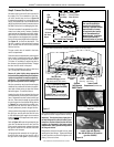
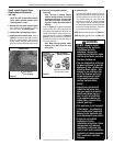
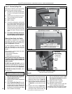
3. Install the hood. Note the location of the
three clips inside the top air channel above
the glass enclosure panel. The clips are
equally spaced on the top surface of the air
channel opening. If needed, use a screw-
driver to open the clips slightly. Engage
the back edge of the hood into the clips to
secure.
Removing the Glass Enclosure Panel
1. Refer to Figure 25. To access the spring
latches securing the front glass enclosure
panel, open the lower control compartment
door by lifting and pulling the bottom panel
forward.
2. Pull the spring latches forward and down to
release them from the lower door channel.
3. Pull the bottom of the glass enclosure panel
out a few inches, and grasp it on the right
and left sides. Gently lift to release the panel
from its upper channel, and then pull the
enclosure panel forward to remove it.
4. Visually inspect the gasket on the backside
of the enclosure panel frame. The gasket
surface must be clean, free of irregularities,
and firmly seated.
This appliance is designed to operate only
when the glass enclosure panel is installed.
Do NOT remove the glass enclosure panel un-
less necessary (e.g., to gain access to compo-
nents within the rebox or to clean the glass).
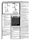
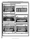
Figure 25
Note: When installing the glass enclosure
panel, make sure spacing on both sides is
even and equal.
Control
Compartment
Panel
Hood
Glass
Door
Header
Spacing
Top
Standoffs
Flush
Nailing
Flange
1/2”
Nailing
Flange
5/8”
Nailing
Flange
Glass Door
Spring Latch
Control
Compartment
Panel
Hood
Glass
Door
Header
Spacing
Top
Standoffs
Flush
Nailing
Flange
1/2”
Nailing
Flange
5/8”
Nailing
Flange
Glass Door
Spring Latch
*IMPORTANT!
Bend up the
Top Standoff
Spacers before
installation.
Use outer pair
for 1/2" materials
and inner pair
for 5/8" materials.
Top
Standoff
Spacers*
Control
Compartment
Panel
Hood
Glass
Enclosure
Spring Latch
Panel
Lower
Enclosure Panel
Flush
Nailing
Flange
1/2"
Nailing
Flange
5/8"
Nailing
Flange
20
NOTE: DIAGRAMS & ILLUSTRATIONS ARE NOT TO SCALE.
Step 9. Install the Glass Enclosure
Panel
Step 10. Burner Air Shutter
Adjustments
(QUALIFIED TECHNICIANS ONLY)
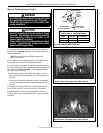
Flame Appearance and Sooting
Proper flame appearance is a flame which is
blue at the base and becomes yellowish-orange
in the body of the ame. When the appliance
is rst lit, the entire ame may be blue and will
gradually turn yellowish-orange during the first
15 minutes of operation. After 15 minutes of
operation, if the ame is blue, or if the ame is
orange with evidence of sooting (black tip), the
air shutter opening may need to be adjusted.
If the air shutter opening is closed too far, sooting
may develop. Sooting is indicated by black puffs
developing at the tips of very long orange flames.
Sooting results in black deposits forming on the
logs, appliance inside surfaces and on exterior
surfaces adjacent to the vent termination.
Sooting is caused by incomplete combustion
in the ames and lack of combustion air enter-
ing the air shutter opening. To achieve a warm
yellowish-orange ame with an orange body
that does not soot, the shutter opening must be
adjusted between these two extremes.
Air Shutter Adjustment Guidelines
• If there is smoke or soot present, rst check
the log set positioning to ensure that the
flames are not impinging on any of the logs.
If the log set is properly positioned and a
sooting condition still exists, then the air
shutter opening should be increased.
• The more offsets in the vent system, the
larger the air shutter opening will need to be.
• An appliance operated with the air shutter
opened too far, may have ames that appear
blue and transparent. These weak, blue and
transparent flames are termed anemic.
• Propane models may exhibit ames which
candle or appear stringy. If this is present and
persists, adjust the air shutter to a more open
position, then operate the appliance for a few
more minutes to ensure that the flame normal-
izes and the flames do not appear sooty.
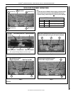
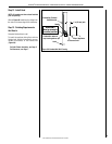
The following chart is provided to aid you in
achieving the correct air shutter adjustment
for your installation.
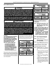
Air Shutter Adjustment Guidelines:
Amount of
Primary Air
Flame
Color
Air Shutter
Adjustment
If air shutter is
closed too far
Flame will
be orange
Air shutter
gap should be
increased
If air shutter is
open too far
Flame will
be blue
Air shutter
gap should be
decreased