


SUPERIOR
®
B-VENT GAS FIREPLACES • MODELS SLBV-35, SLBV-40 • INSTALLATION INSTRUCTIONS
13
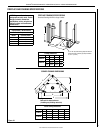
NOTE: DIAGRAMS & ILLUSTRATIONS ARE NOT TO SCALE.
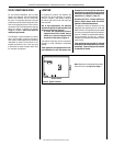
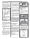
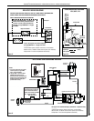
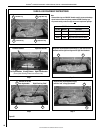
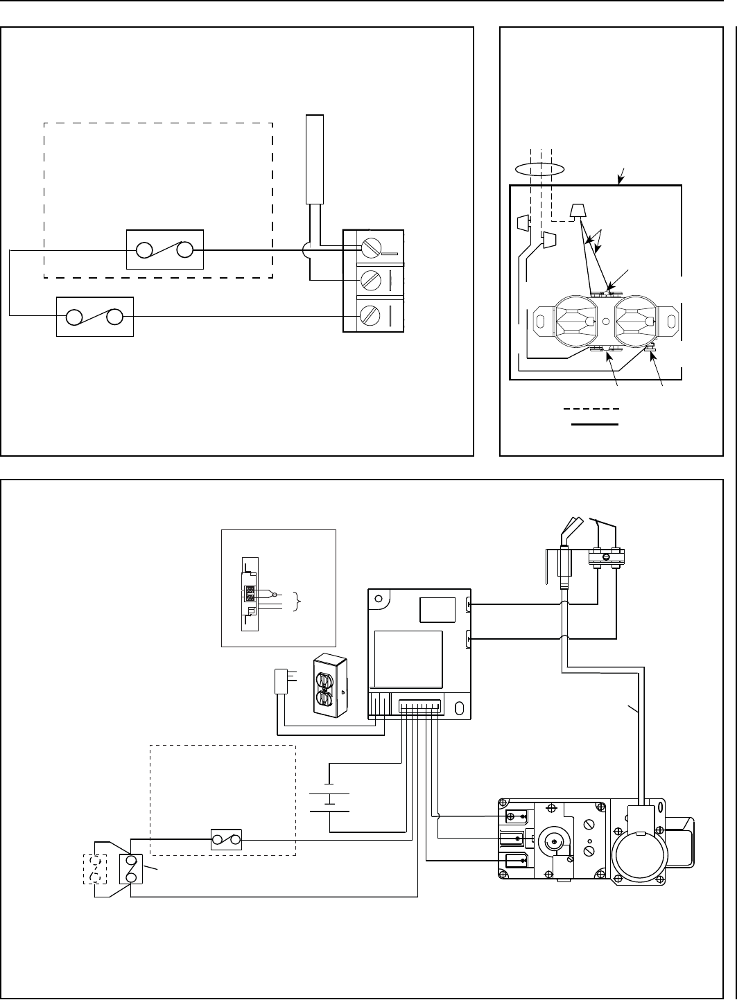
Figure 12
MILLIVOLT WIRING DIAGRAM
CAUTION: WHEN SERVICING CONTROLS, LABEL ALL WIRES PRIOR TO DISCONNECTION.
WIRING ERRORS CAN CAUSE IMPROPER AND DANGEROUS OPERATION.
VERIFY PROPER OPERATION AFTER SERVICING.
If any of the original wire must be replaced,
use Type AWM 105º C - 18 gage wire ONLY.
High Limit Switch
Control Switch*
Gas Control
Valve Terminals
Thermopile
H
I
L
O
W
P
I
L
O
T
P
I
L
O
T
O
N
ti
O
F
F
IN
OUT
TH
TP HTP
T
B-VENT APPLIANCES ONLY: The High Limit
Switch must be factory installed in series,
as shown. If wires to this switch must be
replaced, use Type AWM 200°C - 18 gage
wire ONLY.
_________
*Control switch options: ON/OFF wall switch, unit-mountable
ON/OFF switch, or ON/OFF remote control system (see "Accessory
Components" in the Care and Operation Instructions).
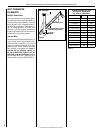
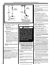
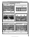
ELECTRONIC IGNITION WIRING DIAGRAM
_________
*Control switch options: ON/OFF wall switch, unit-mountable
ON/OFF switch, or ON/OFF remote control system (see "Accessory
Components" in the Care and Operation Instructions).
TRANSFORMER 3V
BROWN
BROWN
BLACK
BATTERY BACK-UP
BLACK (SENSOR)
BLACK (IGNITER)
IGNITER MODULE
3V
RED
PILOT
IN
OUT
VENT
LO
HI
TH
TP
TH
TP
IN
ORANGE (THTP)
BLACK (TP)
GREEN (TH)
HIGH LIMIT SWITCH
Pilot Burner
Pilot Tube
Assembly
Schematic Representation Only
Electronic Gas Control Valve - DEXEN
B-Vent appliances only - High limit
switch must be factory installed as
shown. If wires to this switch are
replaced, wires must be Type AWM
200°C - 18 gage wire ONLY.
CONTROL
SWITCH *
UNIT MOUNTED
ON/OFF SWITCH,
IF SUPPLIED
Junction Box
J-Box Wiring
BK
W
G
CAV 021
* Control Switches: Wall On/Off
Switch, Unit Mounted On/Off Switch
or Remote Control Switch.
NOTES:
1. If any of the original wire as supplied
must be replaced, use Type AWM
105°C - 18 gage wire ONLY.
2. 120 VAC, 60 Hz - Less than 3 Amps.
CAUTION: label all wires prior to
disconnection when servicing controls.
Wiring errors can cause improper and
dangerous operation. Verify proper
operation after servicing.
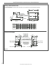
See Figure 14 for detailed drawing of junction box / receptacle wiring.
Figure 13
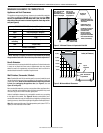
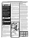
Figure 14
J-BOX / RECEPTACLE
WIRING
120V, 60HZ, 1PH
Green Ground
Screw
Tab Intact
Green
Neutral Side
of Receptacle
120 VAC - Black
Neutral - White
Ground - Green
Junction Box
Field Wired
Factory Wired
Hot Side of
Receptacle
Black
Tab Intact
White
J-BOX/RECEPTACLE WIRING
120V, 60HZ, 1PH