


SUPERIOR
®
B-VENT GAS FIREPLACES • MODELS SLBV-35, SLBV-40 • INSTALLATION INSTRUCTIONS
Step 5. [OPTIONAL] Install Outside
Combustion Air Kit
An optional outside combustion air kit (model
FOAK-4, FOAK-4LD, or DK-4) may be used
with these appliances (see "Installation Acces-
sories," at right).
Refer to the instructions included with the
air kits for specific installation information.
If used, the outside air kit must be installed
before the replace is framed and enclosed in
the finished wall.
Outside air drawn into the fireplace supplies
supplemental combustion air to the re. Only
one outside air duct is necessary, if installed.
If additional length of duct is necessary, pur-
chase locally available U.L. Class 0 or Class 1
metallic ducting. The duct may extend up to 50'
(15.24 m) in one continuous piece.
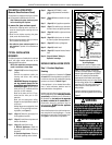
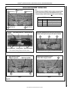
Note: When installing the air duct vertically, do
NOT terminate the duct closer than 3' below
the chimney top.
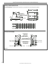
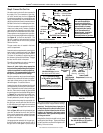
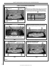
Outside supplemental combustion air ducting
may be run upward or vertically through fram-
ing and ceiling joists, with the hood installed
through an outside wall and 3' (1 m) below the
termination. Ducting may also be run down-
ward through floor joists and under the home
to a ventilated crawlspace not considered part
of the living area of the home.
Note: NEVER terminate an outside supple-
mental combustion air kit in attic space
under any circumstances.
After completing installation of the optional
outside air vent system the outside air control
lever must be put in service and tested to en-
sure proper operation before completing any
enclosure around the rebox.
Failure to do so may result in extensive and
costly rework. Before the operation of the vent
system can be tested, the lever securing screw
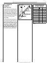
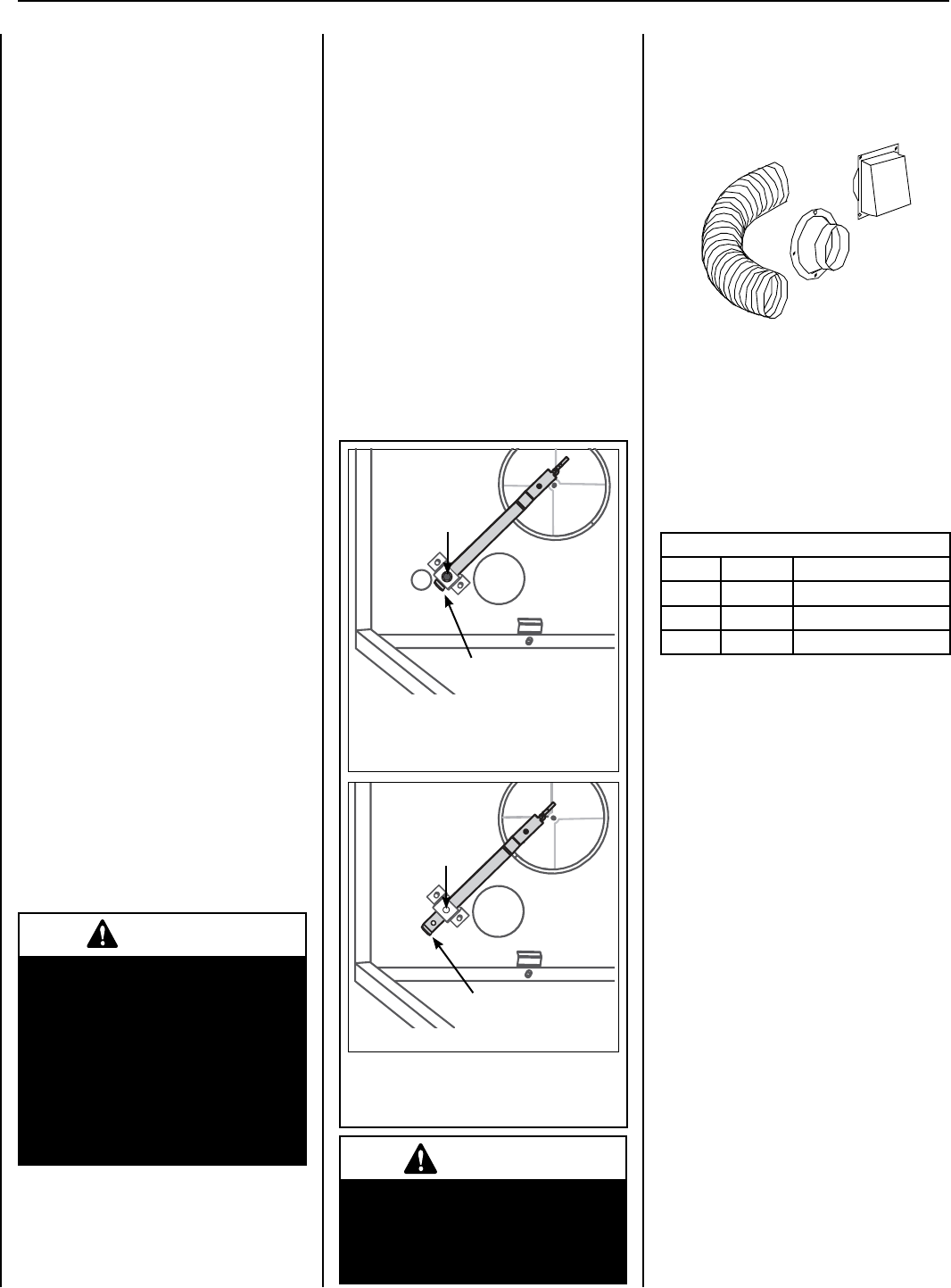
must be removed. See Figure 15.
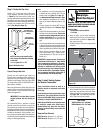
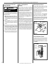
The hand-operated outside air control lever
is located on the left side of the lower control
compartment opening. See Figure 15.
To open the outside air shutter, open the bottom
control access panel, reach into the control com-
partment, and pull the outside air control lever
all the way out. The outside air shutter should
be fully open when the replace is in use and
completely closed when the replace is not being
used. Closing it when not in use will help limit the
amount of outside cold air entering the dwelling.
Operate the actuator through several cycles
including the closed position. Ensuring proper
operation and freedom of movement. Return
the actuator arm to the closed position.
CAUTION
Never locate inlet where it can be
blocked by shrubs, snow drifts,
etc. Never locate inlet in garage
or any area where there is another
fuel burning appliance or products
emitting combustible gases such
as paint, gasoline, etc. In cold
climates, it is recommended the
outside air duct be insulated.
INSTALLATION ACCESSORIES
The following accessory items are available for
use in the installation of this appliance.
Outside Combustion Air Kits
Cat. No. Model No. Description
81L87 FOAK-4 Combustion Air Kit (w/duct)
81L88 FOAK-4LD Combustion Air Kit (w/o duct)
H5377 DK-4 Single 4" Duct Kit
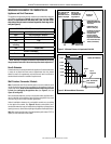
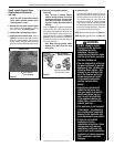
Outside Combustion Air Kits
Models FOAK-4 and FOAK-4LD
Outside combustion air kits are available with
duct (FOAK-4) and without duct (FOAK-4LD)
for use if supplemental outside combustion
air is required or desired. If model FOAK-4LD
is used, it must be used in conjunction with
locally purchased, non-combustible Class 1 or
Class 0 exible duct.
14
NOTE: DIAGRAMS & ILLUSTRATIONS ARE NOT TO SCALE.
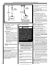
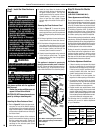
WARNING
Do not operate the shutoff lever
unless a complete outside com-
bustion air system has been
installed with your appliance.
Left Side of
Lower Control Compartment
Figure 15
Securing
Screw
Removed
Outside Air Control
Lever pulled DOWN
(Air Shutter OPEN)
Outside Air Control
Lever pushed UP
(Air Shutter CLOSED)
Securing
Screw
Installed
IMPORTANT: Do NOT move Air Control
Lever if securing screw is installed
(or if not sure it was removed).