


Electronic Appliances
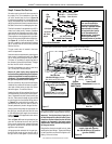
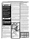
Step 8. Dexen Electronic Valves: Refer to
Figure 34 and the instructions pro-
vided with the kit.
a. Remove and discard the two pres-
sure regulator mounting screws.
b. Remove the pressure regulator and
diaphragm.
c. Discard all removed components.
d. Make sure the provided diaphragm
is installed properly onto the re-
placement pressure regulator.
e. Install the new pressure regulator
using the new screws supplied with
the kit; tighten the screws.
Step 6. (Millivolt systems only): Attach ma-
nometer to the manifold side pressure
test fitting and verify manifold pressure
reads 3.5 inches water column (0.87
kPa) for natural gas, and 10.0 inches
water column (2.49 kPa) for propane
gas.
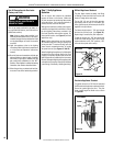
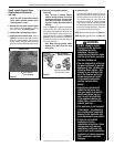
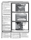
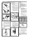
Step 7. (Millivolt systems only): Refer to Figure
33. Remove the pilot hood assembly to
access the hexed pilot orifice. Remove
and replace the orifice with the one
provided in the kit.
Skip to Step 10.
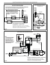
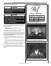
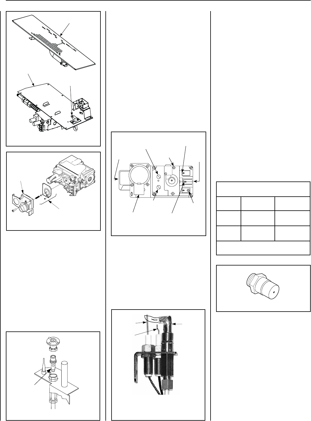
Figure 32: SIT Millivolt System
Pressure
Regulator
Remove
These
Components
Figure 33: SIT Millivolt System
Pilot
Orifice
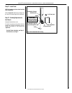
Figure 34: Dexen Electronic Gas Valve
Supply Gas
Inlet
Pressure-Tap
(Manifold)
Regulator
Mounting
Screw
Burner Stage
Terminal
Gas
Outlet
To Burner
Ground (TP)
Pilot Stage
Terminal
Pilot Gas Outlet
Pressure-Tap
(Inlet)
PILOT
OUT
VENT
LO
TH
TP
TH
TP
HI
IN
IN
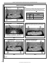
Figure 31: SIT Millivolt System
Burner Assembly
Gas Valve
Assembly
Orifice
Step 11. Reassemble the remaining compo-
nents by reversing the procedures
outlined in the preceding steps.
Step 12. Attach the conversion label (provided
in the conversion kit) next to the rat-
ing plate on the appliance.
Step 13. Turn on gas supply and test for gas
leaks (refer to Page 16).
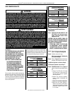
ALWAYS TEST PRESSURES WITH THE VALVE
REGULATOR CONTROL AT THE HIGHEST
SETTING.
All Models
Note the following:
Use pipe joint compound or Teflon tape on
all pipe fittings before installing.
Ensure propane-resistant compounds are
used in propane applications.
Do NOT use pipe joint compounds on flare
fittings.
Step 10. Refer to Figure 31.
a. VERIFY PROPER ORIFICE SIZE
BEFORE INSTALLING IT.
b. Remove the orice from the mani-
fold and replace it with the one
provided in the kit. See Table 7 for
orifice sizes for natural and propane
models. Figure 36 illustrates the
orifice. Always check and verify
orifice size.
c. Retrieve the burner. Slide the venturi
tube over the orice.
d. Adjust the burner air shutter as
shown in Figure 26 on Page 21.
Figure 36
Burner Orifice Sizes
Elevation 0-4500 feet ( 0-1372 meters)
Model
Series
Nat.Gas
drill size (inches)
Propane
drill size (inches)
SLBV-35
#48 (0.076")*
H1236•
#56 (0.046")*
62L37•
SLBV-40
#43 (0.089")*
99K75•
#55 (0.052")*
19L52•
Table 7
*
Standard size installed at factory.
• Part /Cat. Number.
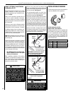
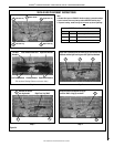
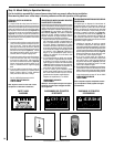
Step 9. Refer to Figure 35. Follow these steps
to replace the pilot orifice:
a. Remove pilot hood assembly to
access the phillipped pilot orifice.
b. Remove and replace the orice
with the one provided with the kit.
Exercise extreme care to prevent
damage to or breakage of the
igniter assembly.
SUPERIOR
®
B-VENT GAS FIREPLACES • MODELS SLBV-35, SLBV-40 • INSTALLATION INSTRUCTIONS
26
NOTE: DIAGRAMS & ILLUSTRATIONS ARE NOT TO SCALE.
Figure 35: Dexen Electronic System
ELECTRONIC
Pilot
Hood
Sensor
Igniter