


SUPERIOR
®
B-VENT GAS FIREPLACES • MODELS SLBV-35, SLBV-40 • INSTALLATION INSTRUCTIONS
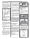
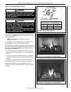
Figure 17
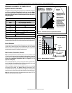
Step 6. Connect the Gas Line
All codes require a shut-off valve mounted in
the supply line. The orientation of the shut-
off valve should face the front. Figure 16
illustrates two methods for connecting the gas
supply. A sediment trap is recommended in the
gas piping within the home to prevent moisture
and debris in the line from damaging the valve.
The ex-line method is acceptable in the U.S.A.
where local codes permit, however, Canadian
requirements vary depending on locality. Instal-
lation must be in compliance with local codes.
These appliances are equipped with a gas flex-
line for use in connecting the unit to the gas line.
See Figure 16 for flex-line description. The
ex-line is rated for both natural and propane
gas. A manual shut off valve is also provided
with the flex-line.
The gas control valve is located in the lower
control compartment.
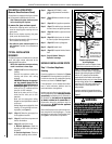
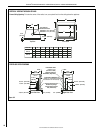
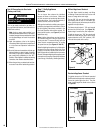
Access the valve compartment by removing the
lower control compartment panel (see Figure
17) by lifting and pulling the panel forward.
The panel is mounted on supporting tabs at
the extreme right and left hand sides. Engage
the tabs into the reliefs in the panel.
The millivolt and electronic control valve has a
3/8" (10 mm) NPT thread inlet port.
Secure all joints tightly using appropriate
tools and sealing compounds (ensure propane
resistant compounds are used in propane ap-
plications). It is recommended to seal around
the gas line to prevent cold air leakage.
Gas line connection may be performed largely
outside of the confines of the control compart-
ment and without having to enter the rebox
behind the glass. Proceed as follows:
Acquire the shut-off valve and gas flex-line and
pull the assembly forward out of the compart-
ment. Separate the shut-off valve from the gas
ex-line. Determine the length of pipe needed
to route the gas line from the last fitting (shown
in Figure 9) to a point within the control com-
partment that will allow the shut-off valve to
be easily attached by hand to the gas ex-line.
Using pipe-dressing materials appropriate for
the gas type, securely afx the shut-off valve
to this determined pipe length at a convenient
location outside of the appliance lower control
compartment.
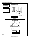
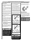
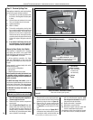
Refer to Figure 18. Insert the last length of gas
pipe with its attached shut-off valve into the
lower control compartment, and pass it through
the gas line access hole on the left side of the
appliance outer wrapper.
Using appropriate materials for the gas type,
thread the last length of pipe into the end of
the gas vent run and tighten in place using a
Length of pipe with attached
Gas Shut-Off Valve in OFF position
(gas line CLOSED)
Figure 18
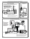
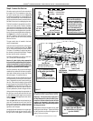
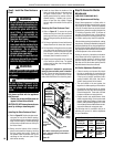
Figure 16: Gas Connection
Gas
Valve
3/8" NPT x
Flare Fitting
3/8" Flex Tubing
3/8" Nipple
3/8" Union
3/8" Close
Nipple
3/8" Shut-off Valve
1/2" x 3/8"
Reducer
Gas
Stub
1/2" x 3/8" Flare
Shut-off Valve
Gas Solid Line Connector
Gas Flex Line Connector
*Sediment
Trap
3"
Mi
n
Note: The gas supply
line must be installed in
accordance with building
codes by a qualied installer
approved and/or licensed
as required by the locality.
In the Commonwealth of
Massachusetts, installation
must be performed by a
licensed plumber or gas tter.
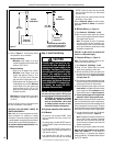
Gas Flex Line
(Gas Shut-Off Valve is behind
door latch; see DETAIL, below)
Gas Control
Valve
Piezo
(Millivolt
units only)
Spring
Door Latch
(one of two)
Lower Control
Compartment
(shaded area)
Optional
Unit-Mounted
ON/OFF Switch
~
{
Note: Millivolt system shown. Electronic system controls are similarly located.
DETAIL:
Gas Shut-Off Valve
in ON position (gas line OPEN)
To shut OFF gas: Turn valve handle
perpendicular (cross-wise) to gas line.
pipe wrench external to the appliance between
the appliance outer wrapper and the framing.
Important: Turn the last piece of gas pipe in
the last fitting until the shut-off valve is posi-
tioned in a way that allows the shut-off valve
handle to be accessed in the lower control
compartment, easily operated throughout its
full range of motion.
Bring the ex-line to the shutoff valve by hand
and align the flare fittings. Tighten the fittings
by hand, and then use wrench to tighten com-
pletely, 1/4-turn at a time.
15
NOTE: DIAGRAMS & ILLUSTRATIONS ARE NOT TO SCALE.
DETAIL: Lower Control Compartment
Door Tab