


8
NOTE: DIAGRAMS & ILLUSTRATIONS ARE NOT TO SCALE.
5
(127)
8-1/4
(20 9)
14
(356)
12
(30 5)
19
(48 3)
4 (102)
2
(51)
4
(102)
6
(152)
8
(203)
10
(254)
12
(305)
6 (152)
10 (254)
14 (356)
12 (305)
8 (203)
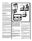
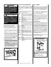
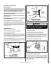
MINIMUM CLEARANCES TO COMBUSTIBLES
uNote: 3 in. (75 mm) above any horizontal /
inclined vent component.
MINIMUM CLEARANCES Inches (millimeters)
Sides 1/2 (13)
Top Spacers 0 (0)
Floor 0 (0)
Bottom of Appliance
To Ceiling
64 (1626)
Vent
3 (76)
Top u
1 (25.4) Sides & Bottom
SERVICE CLEARANCES Feet (meters)
Front & Back Faces 3 ft. (0.9 m)
Table 5
Appliance and Vent Clearances
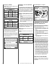
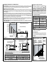
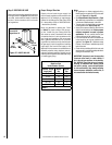
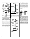
Side Clearances
Combustible materials may project beyond the
sides of the fireplace opening as long as they
are kept within the shaded areas illustrated in
Figure 8.
Hearth Extension - A hearth extension is not required with this appliance. If a hearth extension is used,
do not block the lower control compartment access door. Any hearth extension used is for appearance
only and does not have to conform to standard hearth extension installation requirements.
Wall Finishes / Surrounds / Mantels
Note: Combustible wall finish materials and/or surround materials must not be allowed to encroach
the area defined by the appliance front and back faces (black sheet metal). Never allow combustible
materials to be positioned in front of or overlapping the appliance front and back faces. See Figure
58 on Page 32.
Non-combustible materials, such as surrounds and other appliance trim, may be installed on the
appliance front and back faces with the following exception: If the optional radiant panels are
installed, the non-combustible material may cover any portion of the top radiant panel or the air
gaps surrounding the top radiant panel down to the top edge of eyebrow hood.
The material must
NOT cover any portion of the glass door or louvered panels.
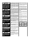
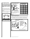
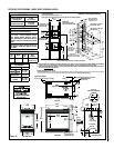
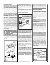
Vertical installation clearances to combustible mantels vary according to the depth of the mantel. See
Figure 6. Mantels constructed of non-combustible materials may be installed at any height above the
appliance opening; however, do not allow anything to hang below the hood.
NOTE: We recommend the use of high temperature paint (rated 175° F or higher) on the under-
side of the mantel.
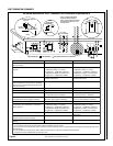
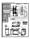
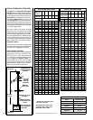
Figure 7 -
Shelf Height Minimum Clearances
Shelf Height
(see table)
Shelf Above Fireplace With Side Venting
Do not insulate this space
above the appliance.
Shelf Height
(see table)
Shelf Above Fireplace With Top Venting
To achieve the lowest possible shelf height, use the side vent outlet. Do not insulate space between
appliance and the area above it. Maintain the minimum height from appliance base to the underside
of combustible materials (used to construct a utility shelf) as shown here.
Do not insulate this space
above the appliance.
Minimum Distance to
Unprotected Side Wall
Top View
Fireplace
Combustible Materials Allowed In
Shaded Area “Safe Zone.” Com-
bustible Walls shown in dark gray.
45
o
Protected wall
shown in white
Inches (millimeters)
At 14" mini-
mum side wall
clearance, a
combustible wall
can project to any
length.
At 8-1/4" side
wall clearance,
a combustible
wall can project
12"
Front or Rear Face
of Appliance
Top of
Appliance
inches (millimeters)
Mantel Depth
Figure 6
Minimum Mantel Clearances
Hood
SDVST & SDVPF Shelf Height - Inches (millimeter)
Side Vent - Straight Out Back Top Vent - with One 90 Degree Elbow
Secure Vent & Secure Flex Secure Vent Secure Flex
41-1/8 (1045) 53-7/8 (1366) 55-5/8 (1410)
Maintain clearances from appliance to
combustible materials as detailed in Table
5, with the following exception: When the
appliance is installed with one side flush
with a wall, the wall on the other side of the
appliance must not extend beyond the front
edge of the appliance. In addition, when the
appliance is installed in the middle of a room, the
side walls surrounding the appliance must not
extend beyond the front edge of the appliance.
See Figure 2 on Page 5.
Figure 8