


NOTE: DIAGRAMS & ILLUSTRATIONS ARE NOT TO SCALE.
26
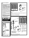
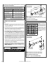
Step 4. FIELD WIRING
Note: The gas valve is set in place and pre-wired
at the factory.
A. SIT and Honeywell Millivolt Wiring
(See Figure 44)
1. Select any of the following optional controls:
wall-mounted switch, wall thermostat or
remote control kit. If appliance-mounted
ON/OFF control is selected mount it in the
gas valve mounting bracket.
2. If wall-mounted ON/OFF control or ther-
mostat is selected mount it in a convenient
location on a wall near the fireplace.
3. Wire the control within the millivolt control
circuit using the 15 feet of 2 conductor wire
supplied with the unit . Caution: Do NOT
connect the optional wall switch to a 120V
power supply.
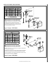
4. Alternatively, the appliance may be operated
without the use of the controls indicated in
Step 1, solely by manipulating the gas valve
control knob. In order to use this method,
twist the free ends of the two conductor wire
(which would otherwise go to an Optional
Control Switch) together as shown in Figure
44.
Note: Wire is located inside the control
compartment.
Note: The supplied 15 feet of 2 conductor wire
has one end of each conductor connected to
the gas valve circuit and the other end of each
conductor placed loose inside the control
compartment.
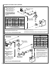
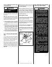
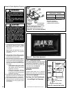
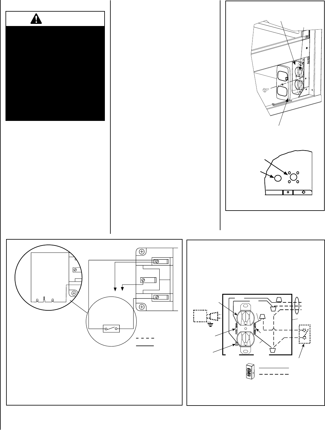
Figure 45 - Blower Wiring Diagram
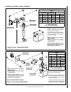
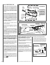
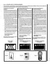
Figure 44 - Millivolt Wiring Diagram
Field Wired
Factory
Wired
TH
TP
TH
TP
u Optional
Control Switch
Thermopile
Schematic
Representation
Only
• If any of the original wire as supplied must be replaced, it must be replaced with Type AWM
105 C - 18 gage wire.
u Optional Kits Installed - ON/OFF wall switch, wall thermostat or remote control receiver.
HT
PT
HT
PT
*
u Twist wires together to operate
unit solely by manipulating the gas
valve control knob; or connect wires
to optional wall thermostat, wall
switch or remote control to operate
unit.
1. If any of the original wire as supplied must be replaced,
1. it must be replaced with Type AWM 105°C – 18 GA. wire.
2. 120V, 60Hz – Less than 3 amps.
Wiring Diagram
Showing the Blower Wiring
for the Optional FBK-100 Kit
Factory Wired
Field Wired
Schematic Representation Only
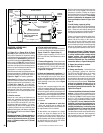
Junction Box
Tab Intact
Tab
Broken
Plug blower
into this
receptacle
n
e
erG
- dnuor
G
*Optional Accessory Switch
Optional
Blower
Ground
etihW - lartueN
120 VAC - Black
Green
Ground
Screw
White
Green
Neutral
Side of
Receptacle
Hot
Side of
Receptacle
Red
Black
*J-BOX WIRING FOR
OPTIONAL (BLOWER
CONTROL) ACCESSORY
SWITCH
�
�
u
CAUTION: Label all wires prior to disconnec-
tion when servicing controls. Wiring errors can
cause improper and dangerous operation.
ATTENTION: Au moment de l'entretien des
commandes, étiquetez tous les fils avant de
les débrancher. Des erreurs de cáblage peu-
vent entraîner un fonctionnement inadéquat
et dangereux.
Verify proper operation after servicing.
S'assurer que l'appareil fonctionne adé-
quatement une fois l'entretien terminé.
CAUTION
Ground supply lead must be con-
nected to the wire attached to the
green ground screw located on the
outlet box. See Figure 45. Failure to
do so will result in a potential safety
hazard. The appliance must be
electrically grounded in accordance
with local codes or, in the absence of
local codes, the National Electrical
Code, ANSI/NFPA 70-latest edition.
(In Canada, the current CSA C22-1
Canadian Electrical Code).
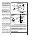
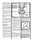
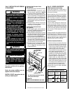
Figure 46
Outlet Receptacle
Junction Box
Field-provided Metal Junction Box
Cover Plate With Screw
View Of Right
Bottom Corner Of Unit
Receptacle, Junction Box
and Cover Plate Installation
Fireplace
Side
Junction Box
knock-out (2
places each side)
Valve Access Side
Press snap
bushing into the
knock-out for
control switch
wires.