


NOTE: DIAGRAMS & ILLUSTRATIONS ARE NOT TO SCALE.
38
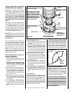
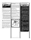
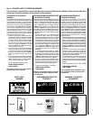
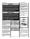
SIT Millivolt Gas Valve
Pilot for SIT Millivolt
Gas Valve
Figure 61
Pressure
Regulator
Remove
These
Components
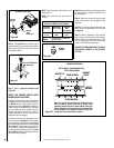
Figure 60
Pilot
Orifice
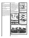
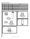
NOTE: Flame appearance will diminish 4% per
thousand feet.
NOTE: Each model has two burners and 2
Orifices.
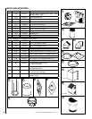
Burner Orifice Sizes
Elevation 0-4500 feet ( 0-1372 meters)
Elevation
Feet (meters)
Natural Gas
drill size (inches)
Propane
Gas
drill size (inches)
0-4500
(0-1372)
#44 (.086") *
60J80 •
#55 (.052")**
19L52 •
Table 9
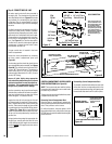
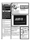
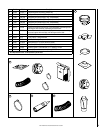
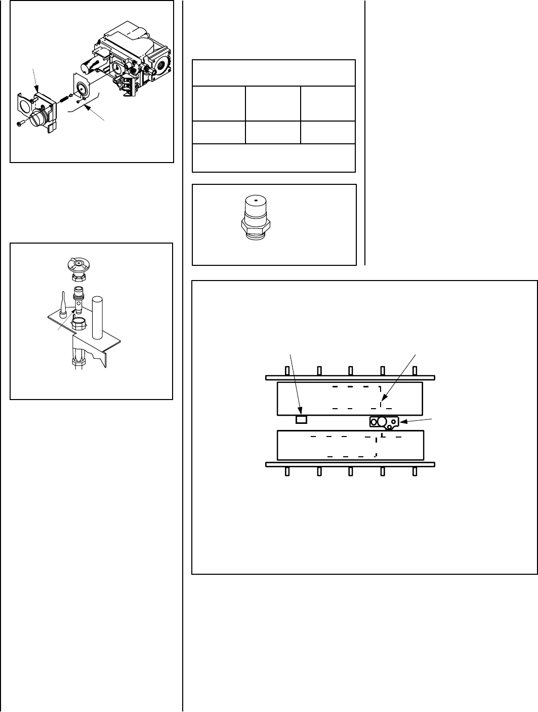
Figure 63
BURNER POSITIONING
REAR BURNER
FRONT BURNER
PILOT
BURNER
Note: The burners are not identical. Position them so
that the circular burner ports run as shown. Note
especially the vertical run of ports relative to the pilot
burner. Bracket A on the rear burner will interfere with
the pilot burner if an attempt is made to install the
rear burner in the front burner’s position.
BRACKET A
BURNER
PORTS
NOTE: INSTALL REAR BURNER FIRST,
THEN FRONT BURNER.
Step 8. Reassemble the remaining components
by reversing the procedures outlined in the
preceding steps.
Step 9. Attach the conversion label provided
in the conversion kit to the rating plate on the
appliance.
Step 10. Turn on gas supply and test for gas
leaks. See Test All Connections For Gas Leaks
on Page 29.
Step 11. Attach manometer to the manifold
side pressure test fitting and verify manifold
pressure reads 3.5 inches water column (0.87
kPa) for natural gas, and 10.0 inches water
column (2.49 kPa) for propane gas.
ALWAYS TEST PRESSURES WITH THE VALVE
REGULATOR CONTROL AT THE HIGHEST
SETTING.
Step 6. See Figure 61 and remove the pilot
hood assembly to access the hexed pilot orifice.
Remove and replace the orifice with the one
provided with the kit.
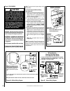
Figure 62
BURNER
ORIFICE
Step 7. (Refer to Figure 59 on Page 37 and
Figure 62)
VERIFY THE PROPER ORIFICE SIZES
BEFORE INSTALLING THEM.
A. Remove the two orifices from the manifold
and replace them with the ones provided in the
kit. Table 9 shows the orifice sizes for natural
and propane models. Figure 62 illustrates the
orifice. Use pipe joint compound or Teflon tape
on all pipe fittings before installing (ensure
propane resistant compounds are used in
propane applications, do not use pipe joint
compounds on flare fittings).
B. Install rear burner first, followed by front
burner, as shown in Figure 63. Ensure that the
arm of the venturi of each burner is hooked onto
the air shutter adjustment lever (refer to Figure
59 on Page 37). The primary air opening can
be adjusted by rotating the adjustment lever
from beneath the firebox floor. Refer to Figure
56 on Page 32 for the recommended minimum
primary air opening setting.
* Standard size installed at factory
** Standard size in LP conversion kit
• Part /Cat. Number