


8
NOTE: DIAGRAMS & ILLUSTRATIONS NOT TO SCALE.
40⁵⁄₈
(1032)
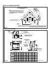
Back wall of chase/enclosure
(including any finishing materials)
a
8³⁄₁₆ (208)
b
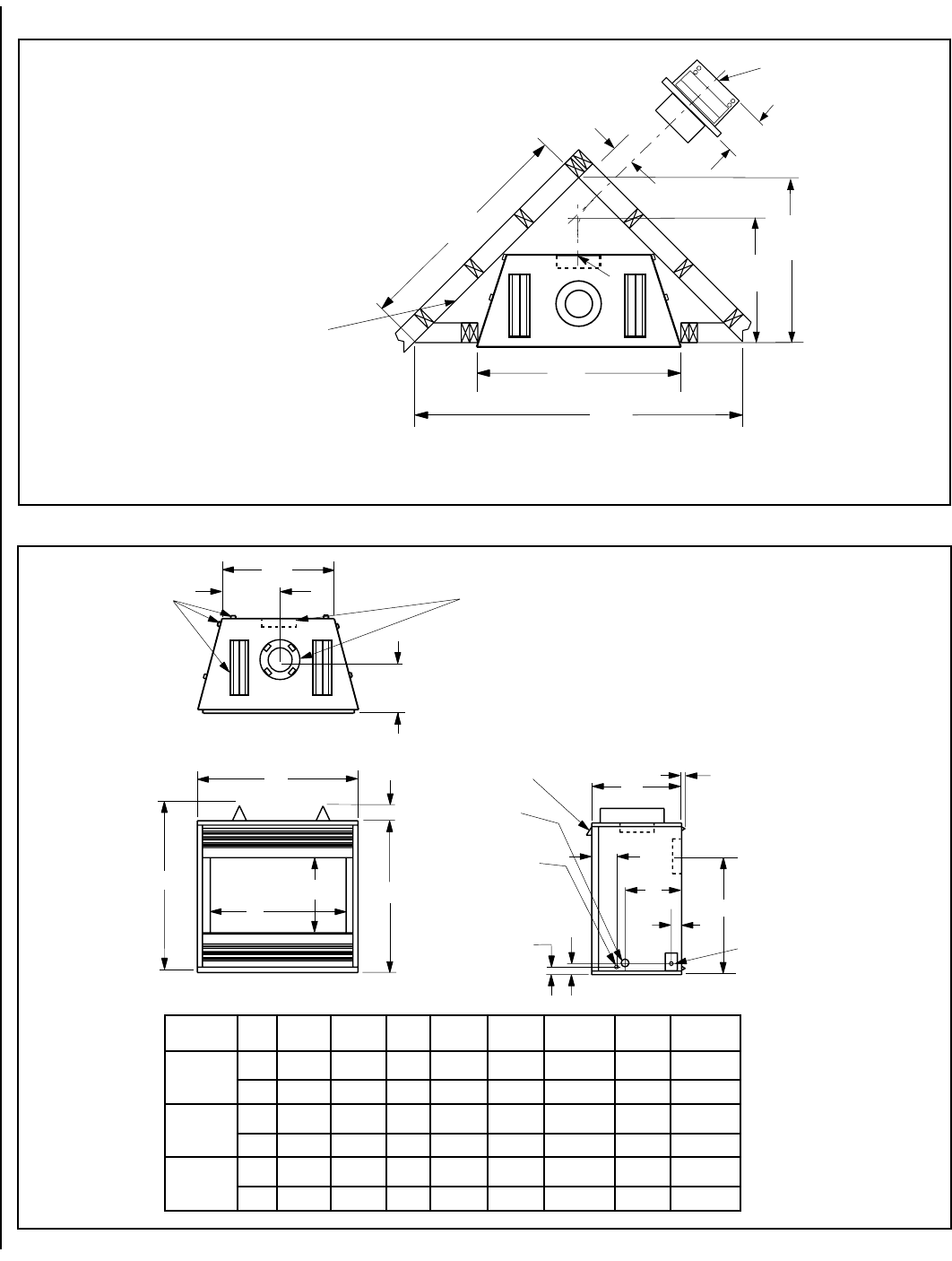
Note-
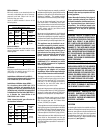
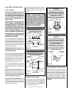
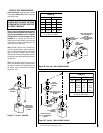
Venting requirements for rear vent applications in corner
installations for D-500, DT-500 AND DR-500 models only -
- the round termination (SV4.5HTR) may not be used
- the horizontal vent length “a” to “b,” must not exceed 28
inches (711 mm)
*19³⁄₁₆
(487)
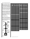
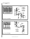
Inches
(millimeters)
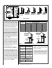
*These dimensions occur when one 45
degree elbow is connected directly to the
appliance collar.
*6¹⁄₈
(156)
28³⁄₄
(730)
35¹⁄₈
(892)
57¹⁄₂
(1461)
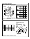
ledoM
.oN
ABCDE F**GH
005-D
005-TD
005-RD
.ni8/1538/123912/1928/15361/11128/742161/72
mm298618384947298155236613
006-D
006-TD
006-RD
.ni8/1048/173422/1438/10461/11628/792161/514
mm91013490166789101876957973
008-D
008-TD
008-RD
.ni8/1048/173422/1938/15461/11628/74361/771
mm641134901630016411876688344
G
E
B
D
C
F**
H
16
(406)
¹⁄₂ (13)
3 (76)
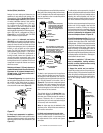
Top View
*CONCENTRIC FLUE
FLUE - 4¹⁄₂ (114)
COMBUSTION AIR - 7¹⁄₂ (190)
FRAMING
SPACERS
(Top and Sides
and Rear)
GAS INLET
(Either Side
and bottom)
* D models have a top and rear vent
DR models have only a rear vent
DT models have only a top vent
Front View
3 (76)
(Louvered Front Model Shown)
**Rear vent models only
ELECTRICAL INLET
2³⁄₄ x 2 (70 x 51) COVER
PLATE with KNOCKOUT)
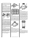
Right Side View
9
(229)
A
1³⁄₈
(35)
OPTIONAL ELECTRICAL
INLET KNOCKOUT
REQUIRING A FIELD
PROVIDED JUNCTION
BOX (Either Side)
(140)
5¹⁄₂
9³⁄₈
(238)
2
(53)
NOTE - Hood shown as
positioned in louvered
front model.
Figure 12
Figure 11
CORNER FRAMING WITH SMALL SQUARE HORIZONTAL TERMINATION(SV4.5HTSS)
FOR D-500, DT-500 AND DR- 500 MODELS ONLY)
FIREPLACE SPECIFICATIONS
**Rear Vent Units Only.
FIREPLACE FRAMING SPECIFICATIONS