


10
REQUIRED ABILITY
Installation and service of this boiler requires ability equivalent to that
of a qualied agency (page 2) in the eld involved. Plumbing and
electrical work is required.
GENERAL
The installation must conform with these instructions and the
local code authority having jurisdiction and the requirements of
the power company. In the absence of code requirements, follow
NFPA-70 (current edition). In the absence of local codes, the
installation must comply with the latest editions of the National
Electrical Code, NFPA 70 or the Canadian Electrical Code CSA
C22.1. The National Electrical Code may be ordered from:
National Fire Protection Association, 1 Batterymarch Park, Quincy,
MA 02269. The Canadian Electrical Code is available from the
Canadian Standards Association, 8501 East Pleasant Valley Road,
Cleveland, OH 44131.
Do NOT test electrical system before boiler is lled with water,
follow the START UP procedure in the OPERATION section of this
manual.
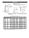
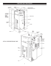
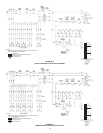
The principal components of the boiler are identied in the Features
and Components illustration on page 8.
Boilers are usually placed in a series with the heating system on
the outlet side of the circulating pump. The boiler piping should
include inlet and outlet water valves to permit maintenance and
service work to be performed without disturbing the rest of the
system.
Detailed system installation drawings are normally provided by the
equipment purchaser or system designer.
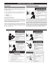
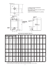
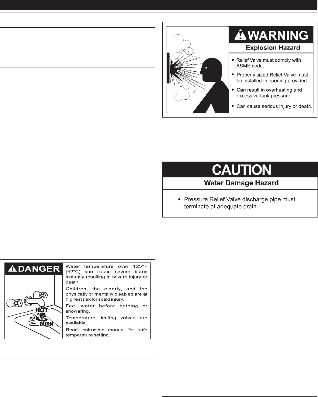
PRESSURE RELIEF VALVE
An ASME rated pressure relief valve is furnished with the boiler. A
tting for the relief valve is provided in the top of the boiler. Never
operate the heating elements without being certain the boiler is lled
with water and a properly sized pressure relief valve is installed in
the relief valve opening provided.
The pressure rating of the relief valve should be equal to or less
than the rated pressure capacity of any component in the system
including the boiler. Should the valve need to be replaced, call the
toll free phone number listed on the back of this manual for further
technical assistance.
A discharge pipe from the relief valve should terminate at an
adequate oor drain. Do not thread, plug, or cap the end of the
drain line.
The Discharge Pipe:
• Shall not be smaller in size than the outlet pipe size of the valve,
or have any reducing couplings or other restrictions.
• Shall not be plugged or blocked.
• Shall not be exposed to freezing temperatures.
• Shall be of material listed for hot water distribution.
• Shall be installed so as to allow complete drainage of both the
relief valve and the discharge pipe.
• Must terminate a maximum of six inches above a oor drain or
external to the building. In cold climates, it is recommended that
the discharge pipe be terminated at an adequate drain inside the
building.
• Shall not have any valve or other obstruction between the relief
valve and the drain.
Once the boiler is installed and lled with water and the system is
pressurized, manually test the operation of the pressure relief valve.
See the maintenance section of this manual forinstructions.
WATER LINE CONNECTIONS
The boiler may be installed by itself, or with a separate storage tank,
on both single and two-temperature systems. When used with a
separate storage tank, the circulation may be either by gravity or
by means of a circulating pump. When a circulating pump is used
it is important to note that the ow rate should be slow so that there
will be a minimum of turbulence inside the heater.
INSTALLATION