


37
Servicing should only be performed by a Qualied Service Agent
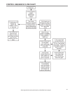
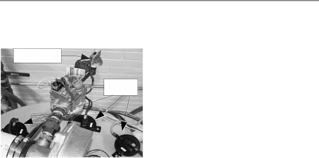
CONTROLS – PRESSURE SWITCHES – ALL MODELS
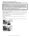
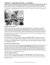
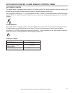
All SUF models are provided with four pressure switches. These switches are essential to the safe and
proper operation of the unit. The switches are wired to the central control board (CCB) individually and
each is monitored individually. The (CCB) is set up to shut the unit down whenever there is a failure of any
of the switches and declare a fault for each individual switch. It is important to understand the purpose of
each switch.
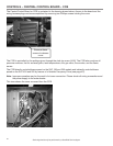
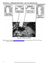
Low Gas Pressure
Switch
Pressure
Switches
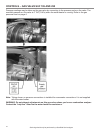
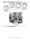
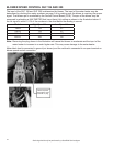
BLOWER PROVING SWITCH
The Blower Proving Switch is provided on the heater to verify that the fan is operating. It is a positive
pressure switch whose electrical contacts are normally open. The blower proving switch electrical
contacts will close on a rise in pressure as the blower increases the pressure in the burner. This switch
is connected to the burner tap by a piece of Tygon (soft plastic) tubing. This tubing must be connected in
order for the switch to close the electrical contacts. The controller requires that the electrical contacts on
this pressure switch be open before it will allow the blower to come on. The control will declare a fault on
the UIM if either condition occurs.
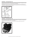
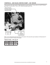
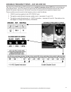
BLOCKED OUTLET PROVING SWITCH
The blocked outlet proving switch electrical contacts are normally closed. The blocked outlet proving
switch electrical contacts will open on a rise in pressure. Check to see if the condensate is allowed to
flow freely from the exhaust elbow and for obstructions in the exhaust venting and exhaust vent terminal.
Also check that the equivalent feet of vent pipe for the specific model has not been exceeded. Check the
vent length tables on page 11.
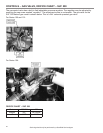
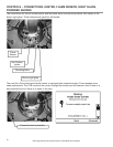
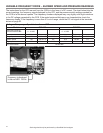
BLOCKED INLET PROVING SWITCH
The Blocked Inlet Proving switch electrical contacts are normally closed. The blocked inlet proving switch
electrical contacts will open when an increase in negative pressure (vacuum) occurs in the intake
vent pipe. The switch is connected to the pressure tap on the PVC flange connected to the inlet of the
blower. When this switch prevents the unit from igniting, most likely the intake is blocked by some means.
Verify that the air intake pipe and air intake vent terminal are free of obstructions that may prevent air
from entering the unit. Also check that the equivalent feet of vent pipe for the specific model has not been
exceeded. Check the vent length tables on page 11.
LOW GAS PRESSURE SWITCH
The Low Gas Pressure Switch electrical contacts are normally open. The low gas pressure switch
electrical contacts will close on a rise pressure. The contacts will open when the pressure falls below
the fixed set point. If this happens during a heating cycle the burner will be shut down and a fault will be
declared on the UIM.