


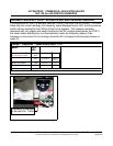

ULTRAFORCE COMMERCIAL GAS WATER HEATER
SUF 120 thru 400 SERVICE HANDBOOK
State Water Heaters – Technical Training Department 32 Ashland City, Tennessee © 2009
Servicing should only be performed by a Qualified Service Agent 198152-002
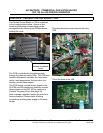
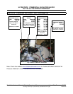
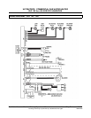
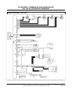
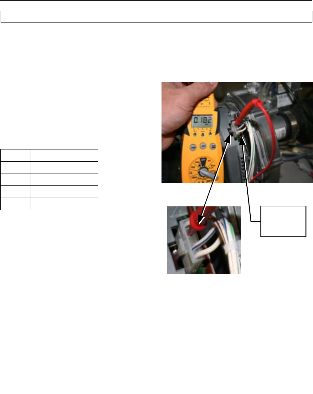
BLOWER SPEED CONTROL SUF 199 AND 250
The input of the SUF 199 and SUF 250 is
determined by the blower. The input of the
water heater may be determined by clocking
the meter as shown on page 5 or by making
sure the blower i s receiving the proper Hz
signal. The blower rpm is controlled by the
Central Control Board (CCB). The signal to
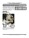
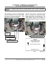
the blower may be measured by attaching a
MULTIMETER that has a Hertz (Hz) setting
as shown in the illustration to the right. If the
Hz signal is within +/
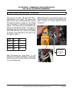
Model Hz Hz
199 N 133
87
250 N 133
87
199 LP 200
156
250 LP 266
96
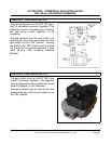
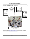
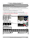
Note: R emoving the plug show n in the
illustration will cause the blower to accelerate
and the input of the water heater to increase
to a much higher rate.
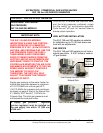
Meter black lead is connected to ground (not
shown) and the red lead is connected to an
open te rminal o n bl ower spee d con trol
connection.
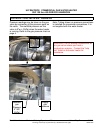
Meter red probe
connected to
open terminal on
plug