


ULTRAFORCE COMMERCIAL GAS WATER HEATER
SUF 120 thru 400 SERVICE HANDBOOK
State Water Heaters – Technical Training Department 14 Ashland City, Tennessee © 2009
Servicing should only be performed by a Qualified Service Agent 198152-002
CONTROL OVERVIEW – ALL MODELS
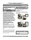
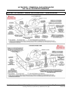
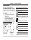
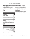
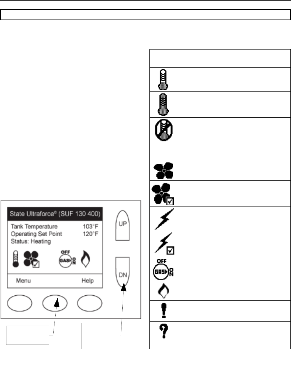
Interaction with the water heater controller is done
through an LCD display called the Universal
Interface Module (UIM).This screen is also referred to
as the “desktop” or “desktop menu”. Up and down
buttons and three operation buttons allow navigation
through the control menus and to make adjustments to
the water heater. Operation of the three lower buttons
is defined immediately above them on the screen.
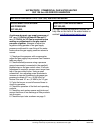
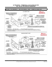
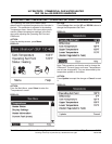
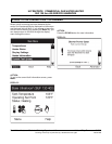
While the water heater is operating, the user interface
will display the desktop screen (if there are no active
faults or warnings).
● An example of this screen is shown below.
● The first temperature on this screen is the
temperature of the water inside the tank.
● The second temperature on this screen is the
Operating Set Point.
● The Operating Set Point is the temperature at
which the water heater will maintain the water
inside the tank.
● The third line on the screen is a text
description of the Operational State of the
water heater. The operating state of the water
heater is also indicated graphically by status
icons.
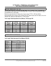
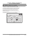
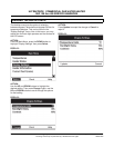
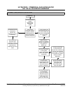
The table of status icons describes graphically
operational details of the water heater. Below is a
legend of all the status icons:
Status
Icon
Description
The temperature of the water in the tank has
fallen and the water heater will now initialize a
new heating cycle.
The temperature of the water in the tank has
reached the Operating Set Point.
The control i s unable t o i nitiate any f urther
heating cycles. This is usually caused by a fault
condition detected by the control, but can also
occur when an external system (like an energy
management sys tem) has as ked t he w ater
heater to discontinue any further heat cycles.
The blower is being energized.
The blower pressure switch has been made.
The igniter has been energized.
The igniter has been energized and sufficient
current for ignition has been detected.
The control has requested that the gas valve
be turned on.
The control has sensed flame in the burner.
The control has detected a fault condition. A
fault condition will cause the water heater to
discontinue operation.
The control has detected a warning condition.
These conditions w ill not cause t he water
heater to discontinue further heating cycles, but
does merit attention.
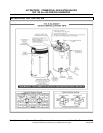
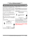
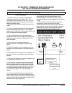
CONTROL OVERVIEW
^
OPERATION
BUTTONS
UP AND
DOWN
BUTTONS