


SUF SERVICE HANDBOOK
INSTALLATION
State Water Heaters Technical Training Department
Ashland City, Tennessee © 2004
3 STC-077
INSTALLATION
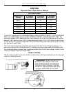
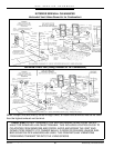
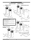
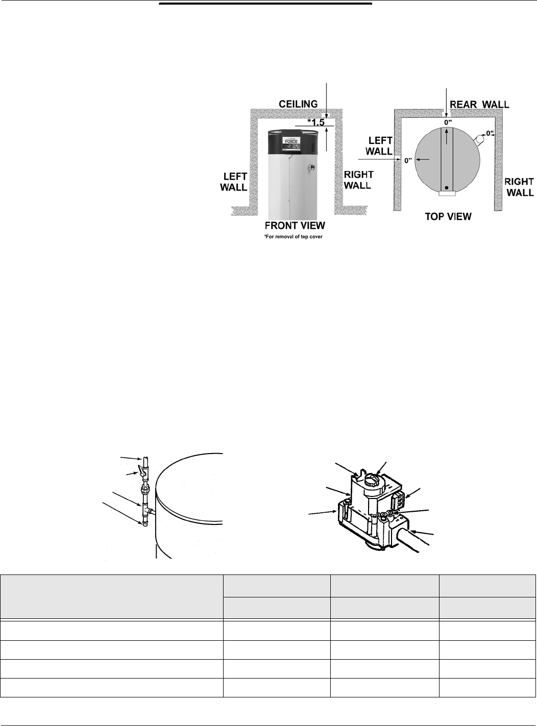
CLEARANCES
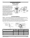
This portion of the handbook will review
often overlooked installation require-
ments. The installation manual covers
these items in detail. SUF water heaters
are approved for installation on com-
bustible flooring. The minimum clear-
ance to combustibles or non-
combustibles is 0 inches from the sides
and rear, 0 inches from vent piping, and
1.5 inches from the top cover. A 24 inch
clearance for all serviceable parts is
recommended. Clearances may vary
between SUF models. See installation
manual or the label on the heater for
your specific model.
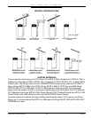
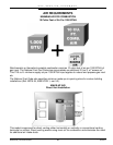
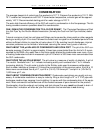
GAS REQUIREMENTS
NOTE: Pressure without capacity will result in lockout. Follow the piping guidelines in the
installation manual. The supply gas pressure is normally measured at the dirt leg or at the inlet gas
pressure tap on the gas valve. This reading must be measured with ‘flowing’ gas.
The manifold gas pressure is measured at the manifold pressure tap on the gas valve when the
gas is flowing. The gas valves used on all SUF water heaters are 24 VAC combination step open-
ing gas valves. They incorporate the main valve and pressure regulator into one body.
GAS SUPPLY SPECIFICATIONS
SUF 240 SUF 150 & 199 SUF 150 & 199
NATURAL GAS NATURAL GAS PROPANE GAS
Max
. Gas Supply Pressure Inches W.C.
12.0 (3 kPa) 12.0 (3 kPa) 14.0 (3.45 kPa)
Nominal Gas Supply Pressure
Inches
W.C.
7.0 (1.75 kPa) 7.0 (1.75 kPa) 11.0 (2.74 kPa)
Minimal Gas Supply Pressure
Inches
W.C.
5.5 (1.37 kPa) 4.5 (1.12 kPa) 11.0 (2.74 kPa)
Manifold Pressure
Inches
W.C.
4.0 (1 kPa) 3.5 (0.8 kPa) 10.0 (2.5 kPa)
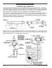
REGULATED GAS SUPPLY LINE
MAIN GAS
SHUTOFF VALVE
DIRT LEG TEE
PIPE CAP
PRESSURE REGULATOR
ADJUSTMENT
(COVER SCREW)
INLET PRESSURE
TAP
GAS INLET
GAS VALVE ON/OFF
TH & TR TERMINALS
(MAIN VALVE)
MANIFOLD
PRESSURE TAP
GAS OUTLET