


SUF SERVICE HANDBOOK
SERVICE AIDS
Technical Training Department State Water Heaters
STC-077
36 Ashland City, Tennessee © 2004
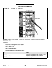
SERVICE AIDS
1. This type product is polarity sensitive. Be certain that your electrical supply wire neutral has
no voltage.
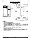
2. This unit will produce condensation — quite heavily at times. The outlet drain hose must be
allowed to drain. Exhaust Vent piping must also drain condensate. Code 11 error would imply
that these must be checked.
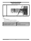
3. If the unit is located in a cold climate, take steps to ensure that exhaust vapors are not pulled
into the air intake. Terminate both pipes on direct vent installations in the same area, but max-
imize the distance between them.
4. Do not combine vent these units.
5. Pushing the reset button at random times may alter setting of the control. Note the sequence of
operation comments on when to push this button.
6. If you make a setting change, cycle the heater with this new setting to lock it into memory.
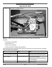
7. The first items to check on a service call
a. Correct venting installation
b. Drainage of condensate from hose and exhaust vent pipe
8. SUF models are certified to 6.800 ft. above sea level with the standard orifice — air and gas.
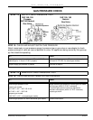
9. The temperature display board indicates average tank water temperature. If one tank sensor is
“open”, the indicator will display the active sensor temperature. (Because the top tank sensor
also contains the high limit-24V-sensor, disconnecting this from the control board results in an
error code (04).)
10. Temperature and pressure relief valve operation. Weeping usually indicates thermal expan-
sion. Large volume discharge usually indicates excessively hot water operation.
11. SUF models are well within decimal level limits, but if you desire to lower the installation level
approximately 6 decibels a muffler (Part No. 195334) may be installed in the exhaust vent.