


5
GENERAL SAFETY
INFORMATION
INSULATION BLANKETS
Insulation blankets available to the general public for external
use on electric water heaters are not approved for use on your
State water heater. The purpose of an insulation blanket is to
reduce the standby heat loss encountered with storage tank
water heaters. Your State water heater meets or exceeds the
National Appliance Energy Conservation Act standards with
respect to insulation and standby loss requirements, making
an insulation blanket unnecessary.
WARNING
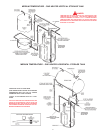
Should you choose to apply an insulation blanket to this heater,
you should follow these instructions (See Figure 1 for
identification of components mentioned below). Failure to follow
these instructions can result in fire, asphyxiation, serious
personal injury or death.
1.
DO NOT COVER THE JUNCTION BOX EXTERNAL WIRING,
THERMOSTATS OR HEATING ELEMENTS ON ELECTRIC
WATER HEATER.
2. DO NOT COVER THE TEMPERATURE-PRESSURE RELIEF
VALVE.
3. DO NOT COVER OPERATING INSTRUCTIONS,
INSTALLATION OR SAFETY RELATED LABELS.
4. DO OBTAIN NEW WARNING AND INSTRUCTION LABELS
FROM STATE WATER HEATERS FOR PLACEMENT ON THE
BLANKET DIRECTLY OVER THE EXISTING LABELS.
5. WATER AND/OR CONDENSATE CAN COLLECT IN AN
INSULATION BLANKET. STATE WATER HEATERS WILL NOT
BE LIABLE FOR ANY RUST OR CORROSION DAMAGE
CAUSED BY THE INSTALLATION OF INSULATION
BLANKETS.
WARNING
FAILURE TO FOLLOW THESE INSTRUCTIONS CAN RESULT
IN SERIOUS PERSONAL INJURY OR DEATH.
EXTERNAL DAMAGE
Do not operate the water heater until it has been fully checked
out by a qualified service technician, if the water heater:
• Has been exposed to fire or damage.
• Produces steam or unusually hot water.
If the water heater has been subject to flooding, it must be
replaced.
INSTALLATION
REQUIRED ABILITY
INSTALLATION OR SERVICE OF THIS WATER HEATER
REQUIRES ABILITY EQUIVALENT TO THAT OF A LICENSED
TRADESMAN IN THE FIELD INVOLVED. PLUMBING AND
ELECTRICAL WORK INVOLVED.
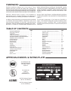
GENERAL
The installation must conform to these instructions and the
local code authority having jurisdiction. Grounding and electrical
wiring connected to the water heater must also conform to the
latest version of the
NATIONAL ELECTRICAL CODE and
NFPA-70. Copies of these codes may be obtained from
American National Standards Institute, 1430 Broadway, New
York, NY 10018.
If your location requires the installation of the water heater to
comply with National Sanitation Foundation requirements, the
heater must be sealed to the floor so as to prevent seepage
underneath the heater. The following are recommended
sealants that may be used on all types of flooring except
concrete: GE Silicone Seal RTV-120, 103, 108 and 109.
DO NOT TEST ELECTRICAL SYSTEM BEFORE HEATER IS
FILLED WITH WATER, FOLLOW START UP PROCEDURE AS
WRITTEN IN “OPERATION” SECTION OF THIS MANUAL.
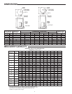
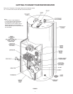
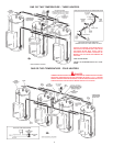
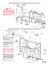
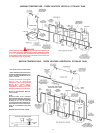
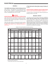
The principal components of the heater are identified in
figure 1. The model and rating plate on page 3 interprets certain
markings into useful information. Both of these references should
be used to identify the heater, its components and optional
equipment.
LOCATION
For proper installation, the heater should be installed on a level
surface.
LOCATE IT NEAR A FLOOR DRAIN. THE HEATER SHOULD BE
LOCATED IN AN AREA WHERE LEAKAGE FROM THE HEATER
OR CONNECTIONS WILL NOT RESULT IN DAMAGE TO THE
ADJACENT AREA OR TO LOWER FLOORS OF THE
STRUCTURE.
WHEN SUCH LOCATIONS CANNOT BE AVOIDED, A SUITABLE
DRAIN PAN SHOULD BE INSTALLED UNDER THE HEATER.
Such pans should be fabricated with sides at least
2” (50.8 mm) deep, with length and width at least 2” (50.8 mm)
greater than the diameter of the heater and must be piped to an
adequate drain. Drain pans suitable for these heaters are
available from your distributor or State Water Heaters, 500
Lindahl Parkway, Ashland City, TN 37015.
Locate the heater close to the point of major hot water usage
and the power supply.
• Try to make hot water piping and branch circuit wiring
as short as possible.
• Insulate hot and cold water piping where heat loss
and condensation may be a problem.
THE HEATER SHOULD NOT BE LOCATED IN AN AREA WHERE
IT WILL BE SUBJECT TO FREEZING.
Suggested clearances from adjacent surfaces are 18 inches
(457.2 mm) in front for access to the controls and elements and
12 inches (304.8 mm) from top. The heater may be installed on
or against combustible surfaces.
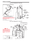
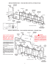
CONNECTIONS
The heater water inlet is located on the side of the heater near
the bottom. The heater outlet is located at the top of the heater.
Piping and wiring diagrams are included in this manual.