


18
Agaslineofsufcientsizemustberuntothewaterheater.Consult
thecurrenteditionofNationalFuelGasCode(ANSIZ223.1/NFPA
54)ortheNaturalGasandPropaneInstallationCode(CAN/CSA
B149.1)andyourgassupplierconcerningpipesize.
There must be:
•Areadilyaccessiblemanualshutoffvalveinthegassupplyline
serving the water heater, and
• Adripleg(sedimenttrap)aheadofgascontrolvalvetohelpprevent
dirt and foreign materials from entering the gas control valve.
•Aexiblegasconnectororagroundjointunionbetweentheshut
off valve and control valve to permit servicing of the unit.
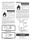
Be sure to check all the gas piping for leaks before lighting the water
heater.Useasoapywatersolution,notamatchoropename.Rinse
off soapy solution and wipe dry.
Usepipejointcompoundorteontapemarkedasbeingresistant
totheactionofpetroleum[Propane(L.P.)]gases.
The appliance and its gas connection must be leak tested before
placing the appliance in operation.
The appliance and its individual Shut-off valve should be disconnected
from the gas supply piping system during any pressure testing of that
systemattestpressuresinexcessof1/2poundpersquareinch(3.5
kPa).Itshouldbeisolatedfromthegassupplypipingsystembyclosing
its individual manual Shut-off valve during any pressure testing of the gas
supply piping system at test pressures equal to or less than 1/2 pound
persquareinch(3.5kPa).
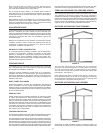
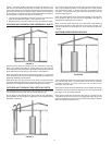
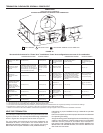
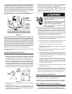
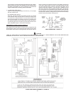
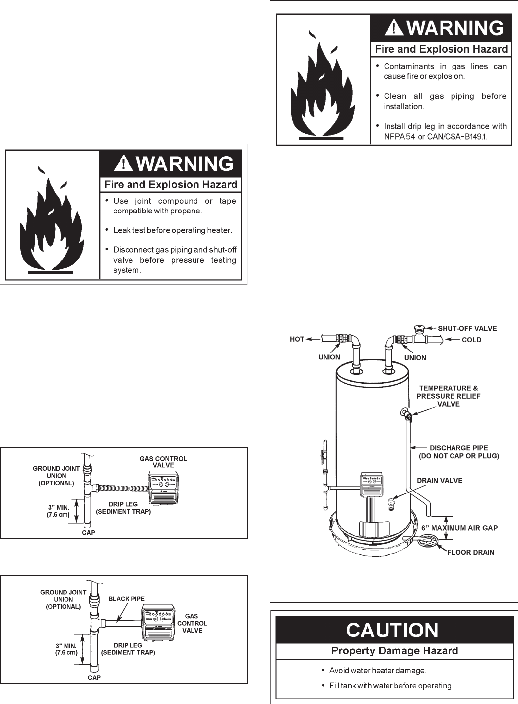
Connecting gas piping to the gas control valve of water heater can be
accomplished by either of two methods shown in Figures 12 and 13.
FIGURE 12. GAS PIPING WITH
FLEXIBLE CONNECTOR.
FIGURE 13. GAS PIPING WITH ALL
BLACK IRON PIPE TO GAS CONTROL.
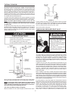
SEDIMENT TRAPS
A sediment trap should be installed as close to the inlet of the water
heater as practical at the time of water heater installation. The
sedimenttrapshouldbeeitherateettingwithacappednipplein
the bottom outlet or other device recognized as an effective sediment
trap.Ifateettingisused,itshouldbeinstalledinconformancewith
one of the methods of installation shown in Figures 12 and 13.
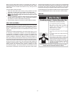
Contaminants in the gas lines may cause improper operation
of the gas control valve that may result in fire or explosion.
Before attaching the gas line be sure that all gas pipe is clean
on the inside. To trap any dirt or foreign material in the gas
supplyline,adripleg(sometimescalledasedimenttrap)must
be incorporated in the piping. The drip leg must be readily
accessible.Installinaccordancewiththe“GasPiping”section.
RefertothecurrenteditionoftheNationalFuelGasCode(ANSI
Z223.1/NFPA54)ortheNaturalGasandPropaneInstallation
Code(CAN/CSAB149.1).
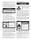
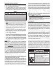
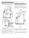
FIGURE 14.
FILLING THE WATER HEATER