


SBN71-120 thru 85-390, SBD30-150/199 TANK TYPE COMMERCIAL
GAS WATER HEATER SERVICE HANDBOOK
tnemtrapeD gniniarT lacinhceT01sretaeH retaW etatS
7002 © eessenneT ,ytiC dnalhsA
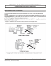
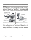
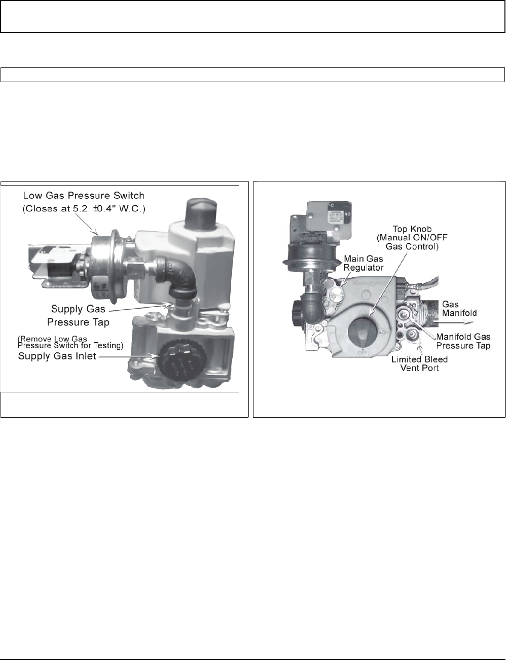
INLET VIEW
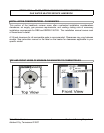
The supply gas pressure is normally measured at the gas valve inlet gas pressure tap, if
available, when the gas is flowing. The manifold gas pressure is measured at the manifold
pressure tap of the gas valve when the gas is flowing. Gas valves used are 24 volt AC
combination-step opening gas valves. They incorporate the main valve and gas pressure
regulator into one body. The Low Gas Pressure Switch, the Supply Gas Inlet, and the Supply
Gas Pressure Tap are shown in the Inlet View to the right.
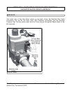
The top view of the gas valve, shown on the right, shows the Main Gas Regulator, Manifold
Pressure Tap, Top Knob, and the Limited Bleed Vent Port. The main gas regulator is found
under the silver cap (silver cap for Natural Gas or black cap for Propane) screw. It is factory
preset to 3.5 inches W.C. and
adjusts gas pressure output from 3.0 to 5 inches water column.
Caution: Always test the
manifold pressure at the outlet when the gas is flowing.
TOP VIEW
GAS VALVE