


22
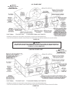
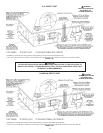
INSTALLATION OF VENT SYSTEM, SIDEWALL
Withtherouteoftheventingsystemandselectionofmaterialscompleted,
as discussed in the section of this manual titled PLANNING THE VENT
SYSTEM,thethroughthewallventterminalinplaceandtherstsection
ofpiping,uptorstelbow,installedatthebloweritistimetocompletethe
installationoftheventingsystemforthesidewallinstallation.
FIGURE 22.
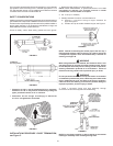
Beforecompletingtheinstallationoftheventingsystembesuretoread
thesectionsofthismanualdiscussingthepropermethodofcuttingand
cementingPVCpipeandttings:VENTPIPEPREPARATION.
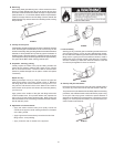
Itisrecommendedthatthecompletionoftheventingsystemstartat
theblowerassemblyandruntothecouplingontheinsidewallofthe
ventterminal,Figure18A.
Theventsystempipingshouldbesupportedevery5feet(1.5m)
of vertical run and every 3 feet (91cm)ofhorizontalrun.Allpiping
andttingsmustbejoinedbytheproperproceduresasdescribed
under: VENT PIPE PREPARATION.
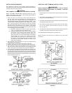
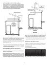
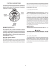
INSTALLATION OF VERTICAL VENT SYSTEM
Aproperashingor“BOOT”shouldbeusedtosealthepipewhereit
exitstheroof.Thetotalventsystemshouldnotexceedtheequivalent
feetofpipeaslistedinTable1.
Providesupportforallpipeprotrudingthroughtheroof.Allpiping
shouldbeproperly secured.Theventsystempipingshouldbe
supportedevery5feet(1.5m)of vertical run and every 3 feet (91cm)
ofhorizontalrun.Allpipingandttingsmustbejoinedbytheproper
proceduresasdescribedunder:VENTPIPEPREPARATION.
FIGURE 23.
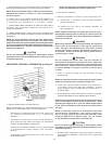
IMPORTANT
Theventsystemmustterminatesothatproperclearancesare
maintained as cited in local codes or the current edition of the
NationalFuel GasCode (ANSIZ223.1)ortheNaturalGasand
PropaneInstallationCode(CAN/CSA-B149.1)andaslistedbelow:
1. VentTerminationmustextendaminimumof18inches(46cm)above
roofor18inches(46cm)abovetheanticipatedsnowleveltoprevent
blockageoftheventtermination,asshowninFigures20and21.
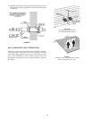
CONCENTRIC VENT INSTALLATION
Thisapplianceiscertiedforconcentricventingwithconcentricvent
kit#9003910105.Followinstructionsbelowforproperinstallations.
KIT COMPONENTS
Eachkitiscomprisedofthefollowing:
Item Description Qty.
Rain Cap 3 in. 1
SDR-26 pipe 4 in. dia. 1
SDR-26 pipe 2½ in. dia. 1
Y Concentric Fitting 3 in. 1
Installation Instructions 194504 1
Field supplied pipe and fittings are required tocomplete the
installation.