


14
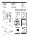
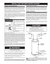
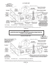
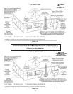
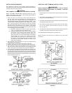
Figures2and10showthetypicalattachmentofthewaterpipingto
thewaterheater.Thewaterheaterisequippedwith3/4inchNPT
water connections.
NOTE: If using copper tubing, solder tubing to an adapter
before attaching the adapter to the water heater connections.
Do not solder the water lines directly to the water heater
connections. It will harm the dip tube and damage the
tank.
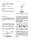
T & P Valve and Pipe Insulation (if supplied)
RemoveinsulationforT&Pvalveandpipeconnectionsfrom
carton.
FIGURE 11.
Fitpipe insulation overthe incoming coldwater lineand the
hotwaterline.Makesurethattheinsulationisagainstthetop
coveroftheheater.FitT&Pvalveinsulationovervalve.Make
sure that the insulation does not interfere with the lever of the
T & P valve.
Secureallinsulationusingtape.
TEMPERATURE-PRESSURE RELIEF VALVE
This heater is providedwith aproperly certified combination
temperature-pressurereliefvalvebythemanufacturer.
Thevalveiscertiedbyanationallyrecognizedtestinglaboratory
thatmaintainsperiodicinspectionofproductionoflistedequipmentof
materialsasmeetingtherequirementsforReliefValvesforHotWater
SupplySystems,ANSIZ21.22•CSA4.4,andthecoderequirements
of ASME.
Ifreplaced,thevalvemustmeettherequirementsoflocalcodes,but
notlessthanacombinationtemperatureandpressurereliefvalve
certiedasindicatedintheaboveparagraph.
Thevalvemustbemarkedwithamaximumsetpressurenotto
exceedthemarkedhydrostaticworkingpressureofthewaterheater
(150psi=1,035kPa)andadischargecapacitynotlessthanthe
water heater
Btu/hrinputrateasshownon thewaterheater’s
modelratingplate.
Forsafeoperationofthewaterheater,thereliefvalvemustnotbe
removedfromitsdesignatedopeningnorplugged.
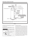
Thetemperature-pressurereliefvalvemustbeinstalleddirectlyinto
thefittingofthewaterheaterdesignedforthereliefvalve.Position
thevalvedownwardandprovidetubingsothatanydischargewill
exitonlywithin6inches(15.2cm)above,oratanydistancebelow
the structural floor. Be certain that no contact is made with any
liveelectricalpart.Thedischargeopeningmustnotbeblocked
orreducedinsizeunderanycircumstances.Excessivelength,
over30feet(9.14m),oruseofmorethanfourelbowscancause
restrictionandreducethedischargecapacityofthevalve,see
Figures10.
Novalveorotherobstructionistobeplacedbetweentherelief
valveandthetank.Donotconnecttubingdirectlytodischarge
drainunlessa6”(15.2cm)airgapisprovided.Topreventbodily
injury,hazardtolife,orpropertydamage,thereliefvalvemust
beallowedtodischargewaterinquantitiesshouldcircumstances
demand.Ifthedischargepipeisnotconnectedtoadrainorother
suitablemeans,thewaterflowmaycausepropertydamage.
TheDischargePipe:
•Shallnotbesmallerinsizethantheoutletpipesizeofthevalve,or
haveanyreducingcouplingsorotherrestrictions.
•Shallnotbepluggedorblocked.
•Shallbeofmateriallistedforhotwaterdistribution.
•Shallbeinstalledsoastoallowcompletedrainageofboththe
temperature-pressurereliefvalve,andthedischargepipe.
•Shallterminateatanadequatedrain.
•Shallnothaveanyvalvebetweenthereliefvalveandtank.