


19
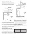
PLANNING THE VENT SYSTEM
Plantherouteoftheventsystemfromtheexhaustelbowtothe
plannedlocationoftheventterminal.
1. Layouttotalventsystemtouseaminimumofventpipeandelbows.
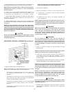
2. Thiswaterheateriscapableofventinguegasesequivalentto
25’(7.6m)of2”pipe,65’(19.8m)of3”pipe,or128’(39.0m)of
4”pipeaslistedinTable1.
TABLE 1
Number of 2” Maximum 3” Maximum 4” Maximum
90° Elbows Pipe - ft. (m) Pipe - ft. (m) Pipe - ft. (m)
1 20(6.1) 60(18.3) 120(36.6)
2 15(4.6) 55(16.8) 112(34.1)
3 10(3.0) 50(15.2) 104(31.7)
4 -- 45(13.7) 96(29.3)
5 -- 40(12.2) 88(26.8)
6 -- 35(10.7) 80(24.3)
Theminimumventlengthsforeachofthepipesizesisone90°plus
2’(61cm)ofstraightpipeandtheappropriatetermination.
NOTE:Theequivalentfeet(m)ofpipelistedaboveareexclusive
of the termination. That is, the termination, with an installed
screen, is assumed to be in the system and the remainder of the
systemmustnotexceedthelengthsdiscussedabove.
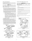
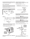
3. Theexhaustelbowassemblyisdesignedtoacceptonlystraight
sectionsof2”pipe.Tostart,aminimumof2”(5.1cm)of2”pipe
mustbeinsertedandgluedtotheexhaustelbowassemblyif
utilizing3”or4”ventpipe.Usethesamemethodwiththeblower
inletifadirectventcongurationisutilized.
If using 2” inch vent pipe:
Aminimumof2”(5.1cm)diameterventpipemustbeattached
totheexhaustelbowassembly.Thetotalsystemcannotexceed
thelengthsdiscussedabove,whereeachelbowisequalto5
equivalentfeet(1.5m)ofstraightpipe.
If using 3” or 4” inch vent pipe:
Twoinches(5.1cm)of2”pipemustbeattachedtotheexhaust
elbowassemblybeforeaddingareducertoacquirethedesired
pipediameter.Anappropriatelysized45degreeelbow(supplied
locally-aschedule40DWV)ventterminalmustbeobtainedwith
anequivalentscreen(suppliedinventkit).Thetotalsystemcannot
exceedtheequivalentpipelengthsdiscussedabovewhereeach
elbowisequalto5feet(1.5m)ofstraightpipe(3”ventpipe)or8
feet(2.4m)ofstraightpipe(4”ventpipe).
U.S. INSTALLATIONS:
NOTE: ThisunitcanbeventedwithPVCpipematerials(CellularCore
ASTM-F891;DWVASTM-D2665orCSAB181.2;Schedule40,80,
120ASTM-D1785orCSAB137.3;orSDRSeriesASTM-D2241or
CSAB137.3),CPVCpipematerials(CPVC41ASTM-D2846orCSA
B137.6;Schedule40,80ASTM-F441orCSAB137.6;orSDRSeries
ASTM-F442),ABSpipematerials(Schedule40DWVASTM-D2661
orCSAB181.1orSchedule40DWVCellularCoreASTM-F628).The
ttings,otherthanthe TERMINATION should be equivalent to PVC-
DWVttingsmeetingASTMD-2665(UseCPVCttings,ASTMF-438
forCPVCpipeandABSttings,ASTMD-2661/3311forABSpipe).
IfCPVCorABSpipeandttingsareused,thenpropercementmust
beusedforalljoints,includingjoiningthepipetoTermination(PVC
Material).IflocalcodesdonotallowtheuseofthePVCtermination
whenamaterialotherthanPVCisusedforventing,thenanequivalent
ttingofthatmaterialmaybesubstitutedifthescreeninthePVC
terminalisremovedandinsertedintothenewtting.
Canadian Installation of this water heater must comply with CAN/
CSA B149.1 - Natural Gas and Propane Installation Code which
requires the vent system components be certied to ULC S636.
ThiswaterheaterhasbeendesigncertiedtobeventedwithPVC
pipecertiedandmarkedascomplyingwithULCS636.Thiswater
heaterissuppliedwitha2inch22.5degreeterminationelbowthatisa
specialttingthatmustbeusedwiththeappliance.Anyoutletpiping,
ttingsandglueusedtoventthisappliancethatisnotsuppliedbythe
manufacturermustcomplywiththeULCS636requirements.
PVCMaterialsshoulduseASTMD-2564GradeCement;CPVC
Materials should use ASTM F-493 Grade Cement and ABS
Materials should use ASTM D-2235 Grade Cement.
Ifthewaterheaterisbeinginstalledasareplacementforanexisting
powerventedheaterinpre-existingventing,athoroughinspection
ofexistingventingsystemmustbeperformedpriortoanyinstallation
work.Verifythatcorrectmaterialasdetailedabovehasbeenused,
andthattheminimumormaximumventlengthsandterminallocation
asdetailedinthismanualhavebeenmet.Carefullyinspecttheentire
ventingsystemforanysignsofcracksorfractures,particularlyat
jointsbetweenelbowsandotherttingsandstraightrunsofvent
pipe.Checksystemforsignsofsaggingorotherstressesinjointsas
aresultofmisalignmentofanycomponentsinthesystem.Ifanyof
these conditions are found, they must be corrected in accordance with
theventinginstructionsinthismanualbeforecompletinginstallation
andputtingthewaterheaterintoservice.
NOTE: A.Forwaterheatersinlocationswithhighambient
temperatures(above100°F)itisrecommendedthatCPVCor
ABSpipeandttingsbeused.B.A22.5degreeelbow(2”vent
pipe)ora45degreeelbow(3”and4”ventpipe)withaninstalled
screen VENT TERMINAL must be used in all cases.
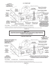
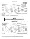
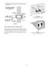
4. There will be some installations where condensate will be formed
inthehorizontalrunsoftheventsystem. This condensate will
runintothecondensateelbow.Thewaterheaterisshippedwith
a condensate hose that attaches to the condensate elbow. No
otherteeorttingisrequired.
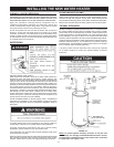
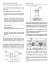
CONDENSATE
Thiswaterheaterisacondensingunitandrequiresadraintobelocatedin
closeproximitytoallowthecondensatetodrainsafely.Thecondensate
drainsfromtheunitattheexhaustteelocatedatthebottomoftheunit
(seegure16).Condensatefromthiswaterheaterismildlyacidic.
Please note that some local codes require that condensate is treated
byusingapHneutralizinglterpriortodisposal.
Caution must be used to ensure that the drain is free and clear of debris
andwillnotallowbackowthroughthecondensatehose.Consideration
mustbegiventoavoidfreezingofthecondensatelineswhichcould
resultinexcessivebuildupofcondensateinsidethewaterheater.
Waterproofheattapemayberequiredtopreventfreezingofthecondensate
lines. Please ensure that the outlet of the condensate drain does
notcreateaslipperyconditionwhichcouldleadtopersonalinjury.
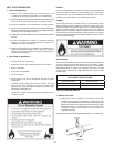
CONDENSATION WARNING: THIS WATER HEATER IS A CONDENSING
UNIT AND REQUIRES A DRAIN TO BE LOCATED IN CLOSE PROXIMITY
TO ALLOW CONDENSATE TO DRAIN SAFELY. THE CONDENSATE
DRAINS FROM UNIT AT THE EXHAUST ELBOW LOCATED AT
BOTTOM OF UNIT. NOTE: IT IS IMPORTANT THAT THE CONDENSATE
HOSE NOT BE ELEVATED ABOVE THE EXHAUST ELBOW, SEE
FIGURE 16. CONDENSATE BUILD-UP WILL BLOCK THE EXHAUST
OUTLET, WHICH WILL CAUSE IMPROPER OPERATION.
FIGURE 16.