


CR/EN (1004) 4.0 Installation 21
CombiPro
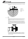
Parallel alignment
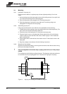
1 Mount dial gauge (A) on the coupling halve motor side, see figure 3.
2 Make index lines on the two coupling halves.
3 Set the dial gauge pointer to zero, turn motor shaft 360 °.
4 Read dial gauge (A). Add or remove shims under the motor until the reading of the
dial gauge is within the allowable tolerance, see paragraph 3.4.4 "Tolerances for
aligning the coupling".
5 Repeat the procedure.
6 Remove dial gauge (A).
Angular alignment
1 Mount dial gauge (B) on the coupling halve motor side, see figure 3.
2 Make index lines on the two coupling halves.
3 Set the dial gauge pointer to zero, turn motor shaft 360 °.
4 Read dial gauge (B). Move the motor sideways until the deflection is halved, see
paragraph 3.4.4 "Tolerances for aligning the coupling".
5 Repeat the procedure.
6 Remove dial gauge (B).
7 Fit the guard. See paragraph 7.4.4 "Assembling the guard".
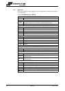
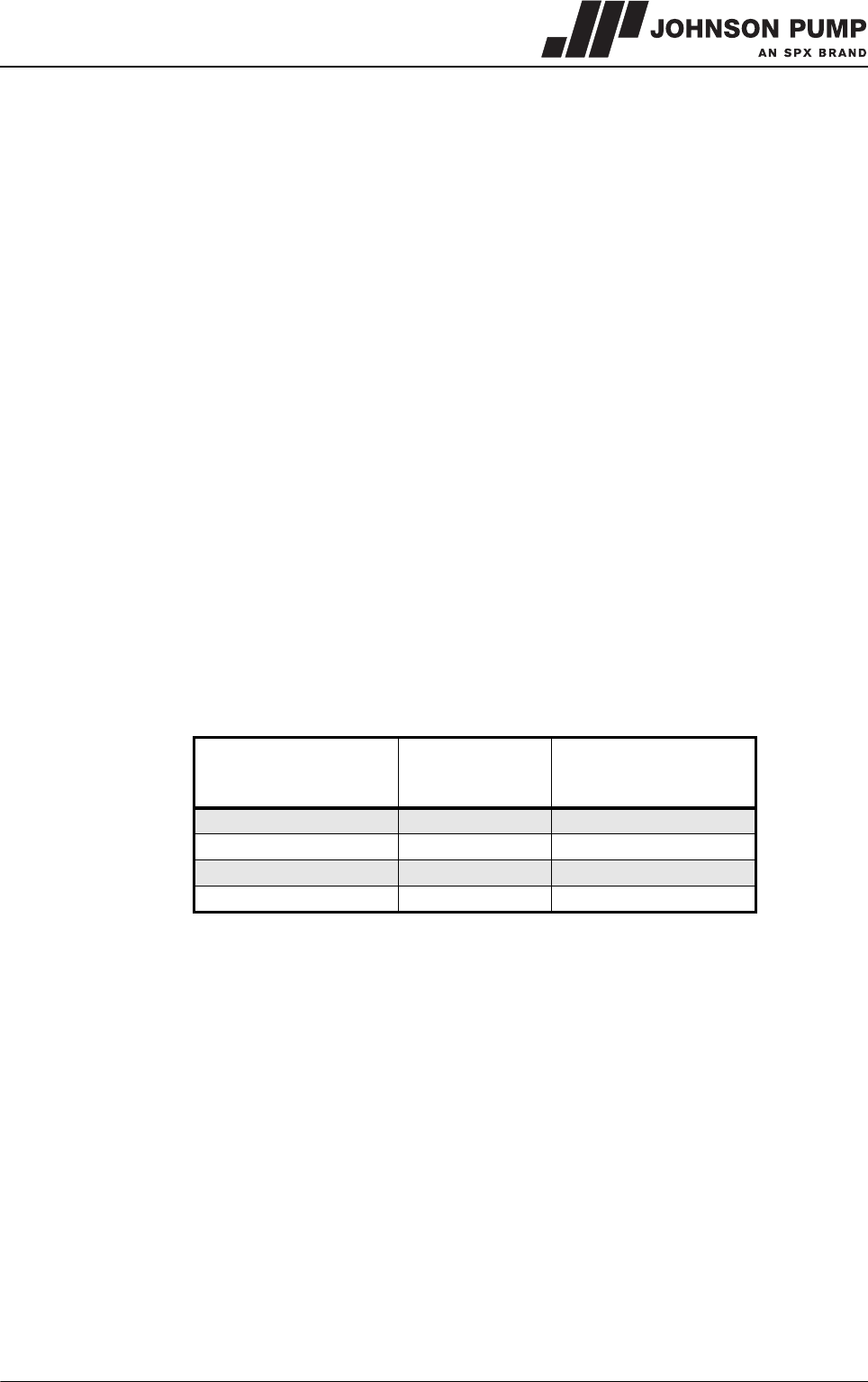
3.4.4 Tolerances for aligning the coupling
The maximum allowable tolerances for the alignment of the coupling halves are shown in
Table 2.
The values are maximums for each type of misalignment. It is recommended that the
coupling is initially aligned to 10% of these values to allow for inevitable movements
during the life of the pump.
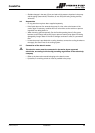
3.4.5 Grouting base plate
Use an approved, non-shrinking grout.
ƽ Grout manufacturer’s instructions should be consulted and followed!
Proceed as follow:
1 Align the base plate with sims under the base plate, see figure 4.
2 Build a strong wooden frame around the base plate to contain the grout.
3 Grout the the wooden frame to the underside of base plate. Allow grout to set.
4 Fill the base plate with grout. Allow grout to dry thoroughly before attaching piping to
pump (48 hours is sufficient time with approved grouting procedure).
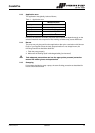
Table 2: Alignment tolerances
External diameter of
coupling [mm]
Axial
misalignment
[mm]
Max. Parallel
misalignment
[mm]
86 1,0 0,30
105 1,3 0,35
130 1,5 0,45
152 2,0 0,55