


Installation instructions
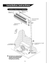
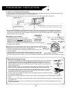
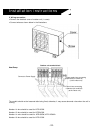
3. Indoor unit refrigeration line installation
l
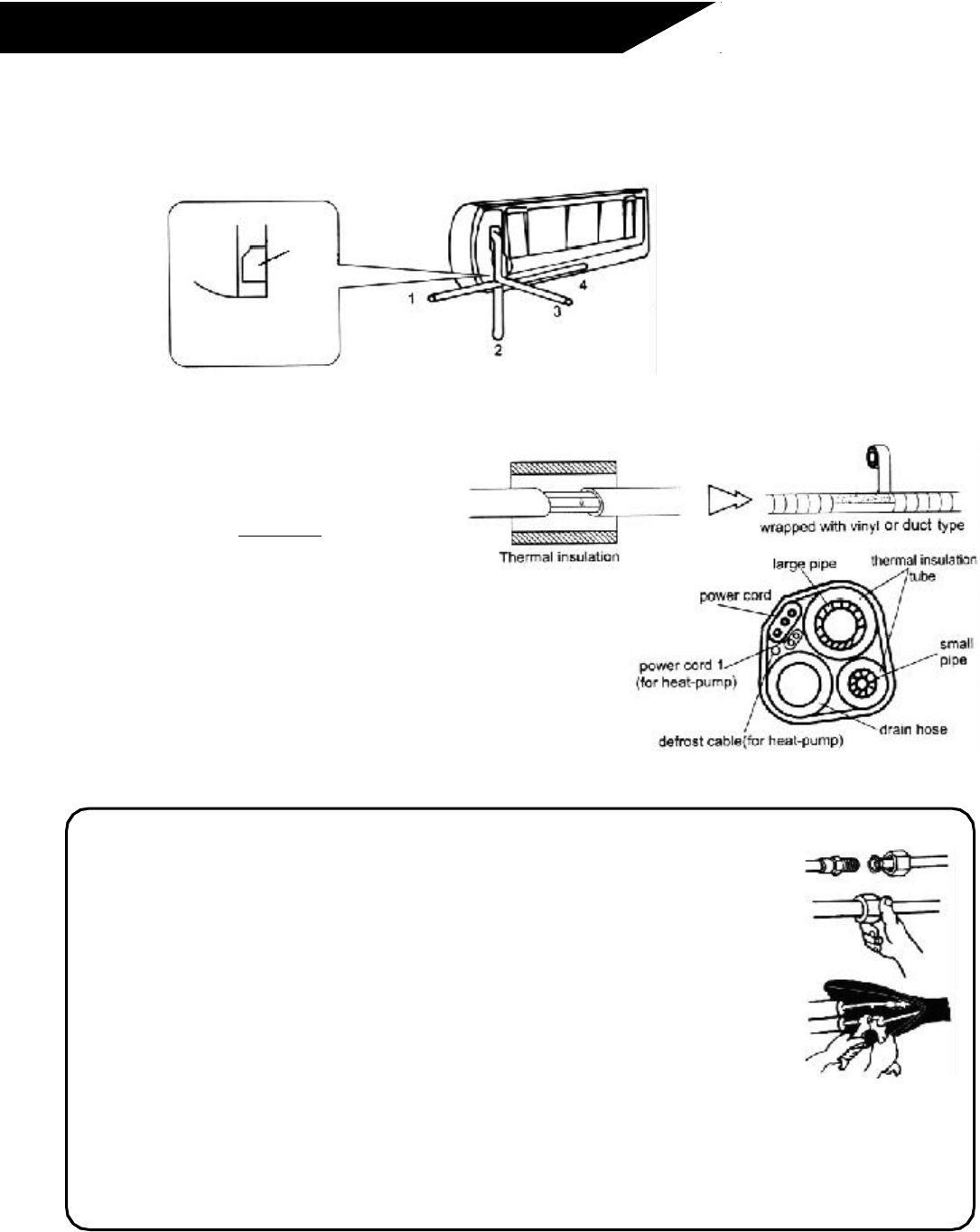
The refrigeration lines and wiring can be routed to the outdoor unit in a number of ways (left or right from the back of the
unit), by using the cut-out access pieces on the casing of the unit.
l
Bend the refrigeration lines carefully to the required positon in order to be aligned with the drilled hole.
l
After connecting refrigeraton lines (see directions below), install the condensate drain line (see page 21+24 for detailed
instructions on connecting condensate drain line). Then connect all wiring (see pages 2 5-27 for detailed instructions on
wiring). After all connections are made, bundle the refrigeration lines, wiring, and condensate drain line together using a
thermal insulation and vinyl/duct tape.
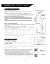
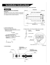
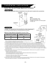
Refrigeration lines insulation:
l
It is important that both the liquid and suction
refrigeration lines are individually insulated to ensure
that they do no sweat and also to maintain proper unit
capacities. This is necessary since the refrigeration is
metered from the outdoor unit and will produce condensation on both refrigeration
lines if not proper insulated.
Refrigeration lines/Condensate drain line/wiring bundle thermal insulation:
l
Place the condensate drain line under the refrigeration lines.
l
Insulation material should be a polythene foam that is approximately a 1/4
inch wall thickness.
l
Condensate drain line should have a downward slope at all times to ensure
proper drainage. Do not allow the drain line to be twisted, horizontal or the
end of the line be immersed in water. If an extension is added to the drain line, make sure that it is also properly insulated.
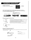
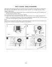
Connection of refrigeration lines:
l
Do not use contaminated or damaged copper tubing for refrigeration lines. If any of the tubing,
evaporator or condenser coils have been exposed to the air for more that 15 seconds, it is
important that they are vacuumed and purged with field-supplied refrigerant. Do not remove
plastic or rubber plugs and brass nuts from the valves, fittings, tubing, or coils until they are
ready to be connected.
l
Use proper tubing cutters to cut the refrigeration lines, advancing the blade of the tubing cutters
slowly. Extra force or improper cutting will cause tubing distortion and also extra burring.
l
Once refrigeration tubes are cut, remove burrs from cut edges with a remover. This will avoid
unevenness on the flare faces, which could cause a gas leak. Hold the ends of the pipes
downward to prevent metal from going into the tubes.
l
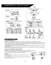
Insert the flare nuts, mounted on the connection ends of both the indoor and outdoor units onto
the ends of the copper tubing.
l
The length of the pipe protruding from the face of the flare die is determined by the particular flaring tool that will be
used.
l
Fix the pipe firmly on the flare die. Match the centers of both the flare die and the flaring punch, and then tighten the
flaring punch fully.
l
Once flaring is complete, connection of the tubing is ready. Align the center of the tubing and tighten the flare nuts
using a torque wrench.
- 18 -
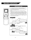
piping direction
cut-out
access
Saw the cut-out access off
along the side of the casing
Note:
When installing the refrigeration lines at the directions 1, 2 or 4,
saw the corresponding cut-out piece off the indoor unit casing.