


Model 5100-XX-IT Toxic Gas Sensor Module
Page: 19
4.4 CONFIGURE SET-POINTS
The sensor module set-points menu is used to initially set-up the alarm set points, relay actions, gas type and
range, 4-20 mA action and RS-485/Sentry address and baud rates.
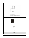
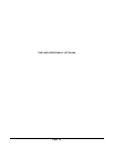
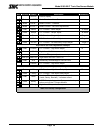
• Alarm Set-points: Once the Set-up menu is selected, press [E] to activate the Alarm Set-point
screen. Use the [▲] or [▼] keys to select Low Alarm or High Alarm menu. Key [▲] will adjust the
setpoint upwards and Key [▼] will adjust the value downwards. Once it reaches the desired
setpoint, Key [E] will accept it and ACK will appear.
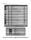
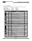
Set-points can be configured using this menu up to the following values:
5100-03-IT O
2
19.5%
5100-04-IT C0
500 PPM
5100-05-IT H
2
S 20 PPM
5100-06-IT Cl
2
5 PPM
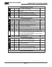
• Alarm Relay Set-up: Once the Set-up menu is selected, press key [▼] once and press [E] to
activate the Relay Set-up menu. Use the [▲] or [▼] keys to select High Alarm or Low Alarm relay
menu and press [E]. Use the [▲] or [▼] keys to select the correct alarm relay action for the
application, Latch, Sentry or Non-Latch. Selecting “Sentry” enables the Sentry controller to make all
alarm action decisions. * indicates the current selection.
• Range: Once the Set-up menu is selected, press key [▼] twice and press [E] to activate the Range
Set-up menu. Use the [▲] or [▼] keys to select Range menu and press [E]. When “Range” is
selected menu provides any choices of ranges available for the gas type selected. Use the [▲] or
[▼] keys to select the desired range. If the “User” range is selected, use the [▲] or [▼] keys to
adjust the high end of the range desired.
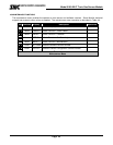
• 4-20mA: Once the Set-up menu is selected, press key [▼] three times and press [E] to activate the
4-20mA Set-up menu. Use the [▲] or [▼] keys to select Calib or CalibOut menu and press [E].
The “Calib” section of the menu allows the user to calibrate the 4 mA and 20 mA outputs. To
calibrate the 4 mA and 20 mA outputs it is necessary to have an amp meter connected to the 5100-
XX-IT and upon selecting the 4 mA output calibration then the [▲] or [▼] keys can be used to adjust
the 4 mA reading on the amp meter until it reads 4 mA. Similar steps can then be performed for the
20 mA output. The CalibOut section allows the user to select the 4-20 mA output action desired
during calibration. * indicates the current selected value. Available selections include:
Track – the 4-20mA value tracks the calibration gas exposed to the gas sensor module
Zero – the 4-20mA value is held at 0mA during calibration
C1.50mA – the 4-20mA value is held at 1.50mA during calibration
C4.00mA – the 4-20mA value is held at 4.0mA during calibration.
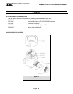
• RS-485 - Once the Set-up menu is selected, press key [▼] four times and press [E] to activate the
RS-485/Sentry Set-up menu. Use the [▲] or [▼] keys to select Address or Baud rate menu and
press [E]. Note that the 5100-XX-IT has a rotary switch on the faceplate and it is used to select
addresses 1-15. When connected to Sentry the user can select 1-8 and using Modbus RS-485 the
user can select addresses 1-15. For Modbus addresses above 15, set the rotary switch to 0 and
then use the “Address” menu to select any address between 16 and 254. The Baud rate menu
allows the user to select a baud rate of 38400, 19200, 9600, 4800 or 2400. * indicates current
selection.