


Page: 7
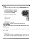
3. INSTALLATION
NOTE
All IT modules are factory are pre-configured and calibrated.
All modules are tagged to indicate the configuration including the sensor module number.
Identify all components during unpacking and install using the factory configuration.
3.1 SENSOR MODULE LOCATIONS
Select locations for each sensor modules based on the following:
• Modules should be placed close to the potential source of gas.
• Modules should be placed in areas accessible for calibration.
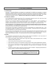
• Sensors should be pointed down and the conduit should include an inverse trap to reduce moisture
(condensation) from accumulating in the electronics enclosure.
• Remote calibration fitting (5360-00) should be used to facilitate calibration gas delivery. Run
polyurethane tubing (1/4” O.D. x 1/8” I.D.) from fitting to an accessible location.
3.2 WIRING
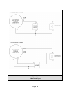
3.2.1 ANALOG 4-20 mA OPERATION
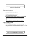
The 4-20 mA output for the 5100-XX-IT can be either 3-wire or 4-wire operation. If using 3-wire operation,
use a minimum of 18 AWG, shielded, 3-conductor cable up to 2000’. For 4-wire operation, use a minimum
of 2 each, 18 AWG, twisted, shielded, pair up to 2000’.
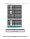
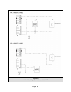
3.2.2 MODBUS OPERATION USING RS-485 CONNECTION
Use a minimum of 18 AWG, 2 conductor for DC power connection. No shield required. In addition use a
minimum of 24 AWG, low capacitance, shielded data cable for RS-485 half duplex communication. The
installation may be planned in a manner which provides up to 32 sensor modules on a single home run.
Refer to Figure 3-3 units ship with BIAS jumpers connected. For all installations, except very long cable
runs, these jumpers connected. The TERM jumpers should be installed in the last (furthest) module of
every loop.
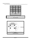
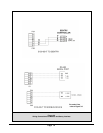
3.2.3 SENTRY OPERATION USING SMC SENTRY CONNECTION
Wire shall be rated as 600 volt tray cable, such as Belden (or equivalent) 27331 or 27331 AS (shielded). If
high RFI or EMI levels exist wiring should be protected by conduit or shield. The installation may be
planned in a manner which provides up to 4 sensor modules on a single home run to a Sentry controller.
NOTE:
Be sure to follow all local electric code and safety requirements when installing the 5100-XX-IT Gas Sensor Module
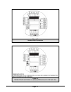
3.2.4 GENERAL
Install conduit as required by local code or construction specifications. When sensor modules are to be
multiplexed for Sentry or RS-485 communication two alternatives may be planned:
• Install splice boxes above each sensor module. Use multi-position positive contact terminals to
connect daisy chain wiring and provide a pigtail to connect to the sensor module transmitter board.