


VICTORY 5
HORIZONTAL PRESSURE VENTING
All VICTORY models are certified for horizontal pressure
venting with the following restrictions:
1. Vent Material
A
. The vent system for horizontal venting must be UL list-
ed single wall Saf-T 3" diameter #AL 29-4C
▲
stainless
steel manufactured by Heat-Fab, Inc. The manufactur-
ers’ part numbers for various items of the vent system
are listed in SLANT/FIN Parts List, Publication # V-
10PL.
B. DO NOT use plastic or galvanized flue pipe.
C. For horizontal, through the wall venting, the 3" flue
c
ollar and adapter MUST be used. The vent pipe size
must be 3" diameter from the boiler to the outside ter-
mination. Certain restrictions on the location of the
vent terminal are specified in APPENDIX "B" and must
be followed.
2
.
Installation
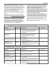
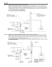
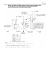
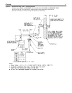
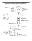
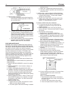
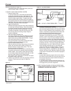
A. Figures 7 and 8 show the allowed venting arrange-
ments. The maximum equivalent vent length is 40 feet
plus vent terminal for all models except V-180 which
has a 20 feet maximum equivalent vent length. Every
90° turn in the vent piping is equivalent to 5 feet of
straight run, (eg. a V-120 system with 3 elbows and the
outside terminal would allow 40 - 15 = 25 feet of
straight run). The minimum allowable equivalent vent
length is 2 feet and 1 elbow plus vent terminal for all
models, see table below. NOTE: For best operation,
elbows should be at least five diameters apart other-
wise maximum vent length should be reduced.
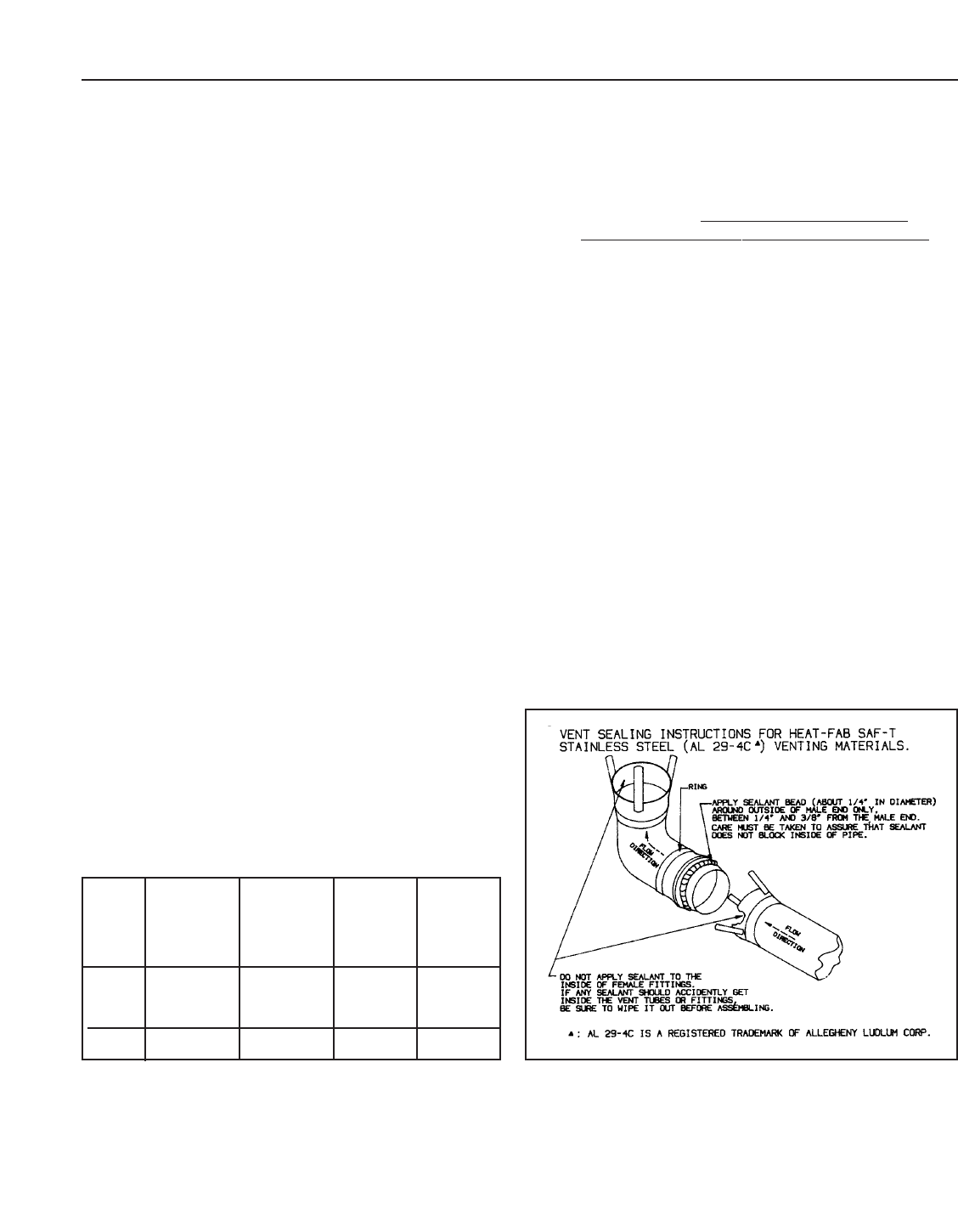
B. When joining the various components of the above list-
e
d vent systems, the man
u
f
a
cturers’
i
nstr
u
ctions
should be closely followed to insure proper sealing.
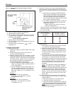
Use GE-RTV 106 or Dow Corning 732 Sealant for
sealing of pipe and fittings. See figure 4 for proper
a
pplication of vent pipe sealant.
C
. All Victory boilers require a condensate drain and drain
trap.
The horizontal pipe must be sloped TOWARD the con-
densate drain at least 1/4" per 1' of run. The horizontal
portion must also be supported with pipe straps at
intervals no greater than indicated by vent pipe manu-
facturer’s instruction.
Where the vent pipe goes through the outside wall, a
thimble must be used (see Figures 7 and 8).
Heat-Fab pipes and fittings
cannot be cut to length.
Use slip joint connector (Heat-Fab part no. 7324GC) to
adjust pipe lengths dimensions.
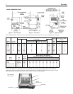
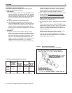
Figure 4. Vent Sealing Instructions
(Consult vent manufacturer’s instructions.)
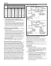
3”
Diameter Venting System Restrictions
Model
Minimum
Length*
Maximum
Equivalent
Length
including
Elbows*
Equiv
alent
Length
of Elbows
Minim
um
No. of
Elbows*
V-33
to 40 ft. 5 ft. 2 ft. 1
V-150
V-180 20 ft. 5 ft. 2 ft. 1
* Vent terminal is in addition to the allowed vent pipe length and elbows.
▲: AL 29-4C is a registered trademark of Allegheny Ludlum Corp.