


VICTORY 1
1
at test pressures equal to or less than 1/2 PSIG.
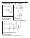
D. All gas piping used should be inspected thoroughly for
cleanliness before makeup. A sediment trap must be pro-
vided, as illustrated on page 2.
E. The minimum and maximum gas supply pressure (at the
inlet of gas valve) are shown on the boiler rating plate for
the type of gas used. Gas supply pressure should never
be less than minimum or more than maximum pressure
when the boiler or any other appliance is turned on or off.
ELECTRICAL CONTROLS AND WIRING
A. The electrical power to the boiler must be on a separately
fused and live circuit.
B. If an external electrical source is utilized, the boiler, when
installed, must be electrically grounded in accordance
with the requirements of the authority having jurisdiction
or, in the absence of such requirements, with the National
Electrical Code, ANSI/NFPA No. 70-latest edition.
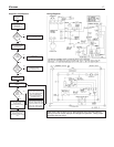
C. Basic control wiring diagrams are given on page 17 and
18. Other control systems may be factory supplied: see
User's Information Manual and instructions packed with
control system supplied.
D. After placing the boiler in operation, the safety shutoff
device must be tested. See page 14 safety check.
BOILER ROOM AIR SUPPLY AND VENTILATION
An ample supply of air is required to obtain combustion and
v
entilation. ALL AIR COMES FROM OUTSIDE, directly
through wall openings to the boiler or through unsealed
openings around windows, doors, etc. in the whole building.
When buildings are insulated, caulked and weather-stripped,
now or later on, direct openings to outside may be required
and should be provided. If the boiler is not near an outside
wall, air may be ducted to it from outside wall openings.
Provisions for combustion and ventilation air must be made
in accordance with section 5.3, Air for Combustion and Venti-
lation, of the National Fuel Gas Code, ANSI Z223.1-latest
edition, or applicable provisions of the local building codes.
The following recommendation applies to buildings of ener-
gy-saving construction, fully caulked and weather stripped:
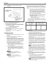
Provide one GRILLED opening near the floor and one near
the ceiling on an outside wall near the boiler (or duct from
such openings to the boiler), EACH opening to be a mini-
mum of one square inch per 2000 Btuh input to ALL APPLI-
ANCES in the area. For a total appliance input of 200,000
Btuh, each opening will be 100 square inches
.
A g
r
illed
opening 10"X10" has 100 square inches of area. If fly
screen must be used over openings, double the area and
inspect and clean the screen frequently.
Openings must never be reduced or closed. If doors or win-
dows are used for air supply, they must be locked open.
Protect against closure of openings by snow and debris.
Inspect frequently.
No mechanical draft exhaust or supply fans are to be used in
or near the boiler area.
The flow of combustion and ventilating air to the boiler must
not be obstructed.
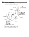
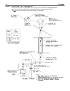
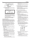
WATER PIPING
I. CIRCULATING SYSTEMS
A. Packaged water boilers are equipped with a water circu-
lating pump, mounted to return the water into the boiler.
For some installations, the pump should be on the sup-
ply main. See PUMP LOCATION, on page 12.
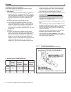
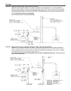
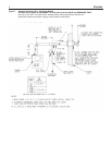
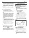
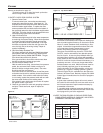
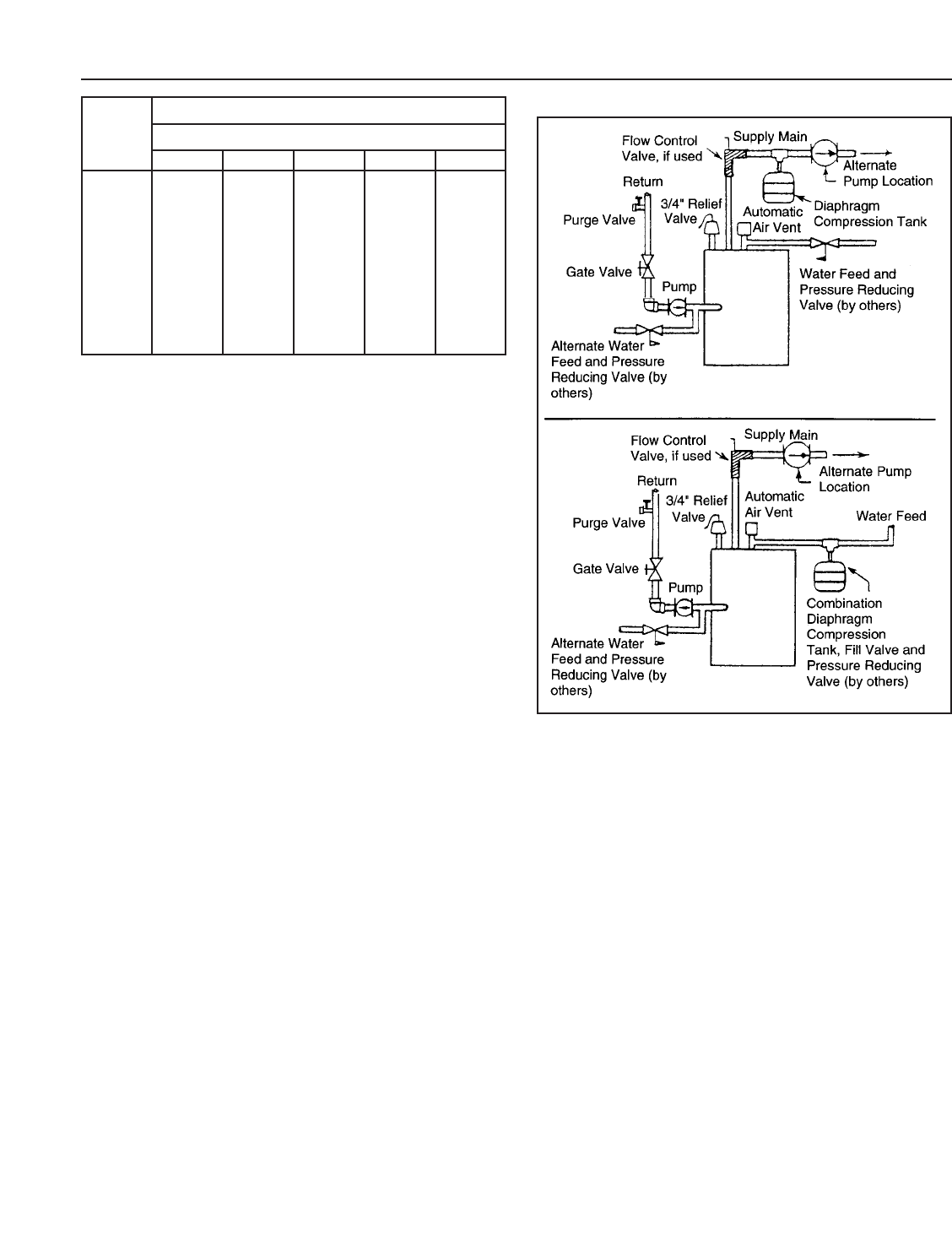
II. AIR CONTROL SYSTEM
A. DIAPHRAGM-TYPE COMPRESSION TANKS are used
to control system pressure in an AIR ELIMINATING
SYSTEM; an automatic air vent is used to REMOVE air
from the system water. See illustration.
If system pressure needs fur
ther control, add an addi
-
tional tank or install a larger capacity tank.
Locate the tank near the boiler, as illustrated.
An automatic air v
ent should be installed in the top of
the
boiler
.
See illustr
ation.
1
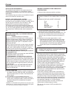
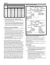
/2 3/4 1 1-1/4 1-1/2
10 132 278 520 1050 1600
20 92 190 350 730 1100
30 73 152 285 590 890
40 63 130 245 500 760
5
0 56 115 215 440 670
60 50 105 195 400 610
70 46 96 180 370 560
80 43 90 170 350 530
9
0 40 84 160 320 490
100 38 79 150 305 460
Length
of Pipe
in Feet
Gas Flow In Piping -- cu. ft. per hr.
Iron Pipe Size (Ips)—inches
Figure 10. Air Eliminating System
At pressure drop of 0.3 in.water, specific gravity = 0.60.