


VICTORY 3
I
NSTALLATION REQUIREMENTS
The installation must conform to the requirements of the
a
uthority having jurisdiction or, in the absence of such
requirements, to the National Fuel Gas Code, ANSI Z223.1-
l
atest edition.
This installation must also conform to the additional require-
ments in this Slant/Fin instruction book.
NATURAL GAS FIRED BOILER LOCATION
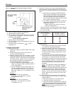
Provide a level, solid foundation for the boiler. Location
should be as near as possible to chimney or outside wall so
t
hat the flue pipe from boiler is short and direct. (See
Appendix B for vent terminal location restrictions.)
The location should also be such that the gas ignition sys-
tem components are protected from water (dripping, spray-
ing, rain, etc.) during appliance operation and service (circu-
lator replacement, condensate trap, control replacement,
etc.).
WARNING
LIQUEFIED PETROLEUM (L.P.) PROPANE FIRED GAS
BOILER LOCATION
REQUIRES SPECIAL ATTENTION
Liquefied Petroleum (L.P.) propane gas is
heavier than air.
Therefore, propane boilers, piping, valves must NOT be
installed in locations where propane leaking from defective
equipment and piping will "pool" in a basement or other
space below the leak.
A spark or flame from the boiler or other source may ignite
the accumulated propane gas causing an explosion or fire.
Provide a level, solid foundation for the boiler. Location
should be as near the chimney as possible so that the flue
pipe from boiler to chimney is short and direct.
The UNIFORM MECHANICAL CODE may be in effect in
your geographic area.
The following precautions are cited by the 1994 UNIFORM
MECHANICAL CODE, section 304.6:
"LPG Appliances. Liquefied petroleum gas-burning
appliances shall not be installed in a pit, basement or
similar location where hea
vier-than-air-gas might collect.
Appliances so fueled shall not be installed in an abo
v
e-
grade under-floor space or basement unless such loca-
tion is provided with an approved means for removal of
unburned gas."
Consult Chapter 5 of the 1994 UNIFORM MECHANICAL
CODE for design criteria of the "approved" means for
removal of unburned gas.
BOILER FOUND
ATION
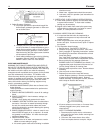
A. Provide a solid, level foundation, capable of supporting
the weight of the boiler filled with water, and extending at
least 2" past the jacket on all sides. See dimensions of
boilers
, page 2.
B. For installation on non-combustible floors only*.
C. If boiler is to be located over buried conduit containing
electric wires or telephone cables, consult local codes or
the National Board of Fire Underwriters for specific
requirements.
* Installation on combustible flooring allowed only with proper Com-
bustible Floor Kit. Kit part number is printed on boiler rating plate.
In no case may the boiler be installed on carpeting.
M
INIMUM CLEARANCES FROM COMBUSTIBLE
CONSTRUCTIONS
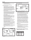
A. Minimum boiler clearances shall be as follows:
VICTORY BOILER
MINIMUM CLEARANCE FOR COMBUSTIBLE CONSTRUC-
TION.
MINIMUM ALCOVE AND CLOSET CLEARANCE.
Front 6"
R
ear 6"
Left Side 6"
Right Side 12"
Top (above boiler) 12"
Flue Connector 6"
B. Provide accessibility clearance of 24" on sides requiring
servicing and 18" on sides used for passage.
C. All minimum clearances shown above must be met. This
may result in increased values of some minimum clear-
ances in order to maintain the minimum clearances of
others.
D. Clearance from hot water pipes shall be 1 inch**.
** At points where hot water pipes emerge from a floor,
wall or ceiling, the clearance at the opening through
the finished floor boards or wall or ceiling boards may
be not less than 1/2 inch. Each such opening shall be
covered with a plate of uncombustible material.
SAFETY
KEEP THE BOILER AREA CLEAR AND FREE FROM
COMBUSTIBLE MATERIALS, GASOLINE AND OTHER
FLAMMABLE VAPORS AND LIQUIDS.
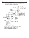
FLUE GAS VENTING REQUIREMENTS
The Victory series boiler is a high efficiency, mechanically
induced draft boiler and, therefore, requires different venting
arrangements than natural draft, lower efficiency boilers.
THE FOLLOWING INSTRUCTIONS MUST BE CAREFULLY
READ AND FOLLOWED IN ORDER TO AVOID ANY HAZ-
ARDOUS CONDITIONS DUE TO IMPROPER INSTALLA-
TION OF THE FLUE GAS
VENTING SYSTEM.
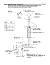
The v
ent piping installation MUST be in accordance with
these instructions and with ANSI Z223.1-latest edition
NATIONAL FUEL GAS CODE, Part 7, Venting of Equipment.
Other local codes may also apply and must be followed.
Where there is a conflict between these requirements
, the
more stringent case shall apply
.
If this boiler is replacing a boiler which is connected to a
common venting system with other natural draft, gas fired
appliances, the removal of the existing boiler from the vent-
ing system is likely to cause the system to be too large for
proper venting of the appliances remaining connected to it.
At the time of removal of the existing boiler, the test proce-
dure specified in Appendix "A" m
ust be followed.
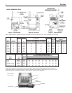
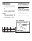
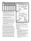
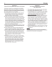
Figure 5 shows the models, vent sizes, conditions and
requirements for different types of venting.
The use of a vent damper is NOT permitted on this
boiler series.