


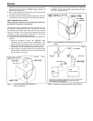
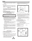
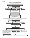
BOILER ROOM AIR SUPPLY AND VENTILATION
An ample supply of air is required to obtain combustion and
ventilation.ALL AIR COMES FROM OUTSIDE, directly through
wall openings to the boiler or through unsealed openings
around windows, doors, etc. in the whole building. When build-
ings are insulated, caulked and weather stripped, now or later
on, direct openings to outside may be required and should be
p
rovided. If the boiler is not near an outside wall, air may be
d
ucted to it from outside wall openings.
Provisions for combustion and ventilation air must be made in
accordance with section 5.3, Air for Combustion and
Ventilation, of the National Fuel Gas Code, ANSI Z223.1-latest
edition, or applicable provisions of the local building codes. The
following recommendation applies to buildings of energy-saving
construction, fully caulked and weather stripped:
Provide one GRILLED opening near the floor and one near the
ceiling on an outside wall near the boiler (or duct from such
openings to the boiler), EACH opening to be a minimum of one
square inch per 2000 Btuh input to ALL APPLIANCES in the
area. For a total appliance input of 200,000 Btuh, each open-
ing will be 100 square inches. A grilled opening 10"X10" has
100 square inches of area. If fly screen must be used over
openings, double the area and inspect and clean the screen
frequently.
Openings must never be reduced or closed. If doors or win-
dows are used for air supply, they must be locked open.
Protect against closure of openings by snow and debris.
Inspect frequently.
No mechanical draft exhaust or supply fans are to be used in or
near the boiler area.
The flow of combustion and ventilating air to the boiler must not
be obstructed.
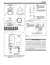
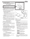
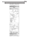
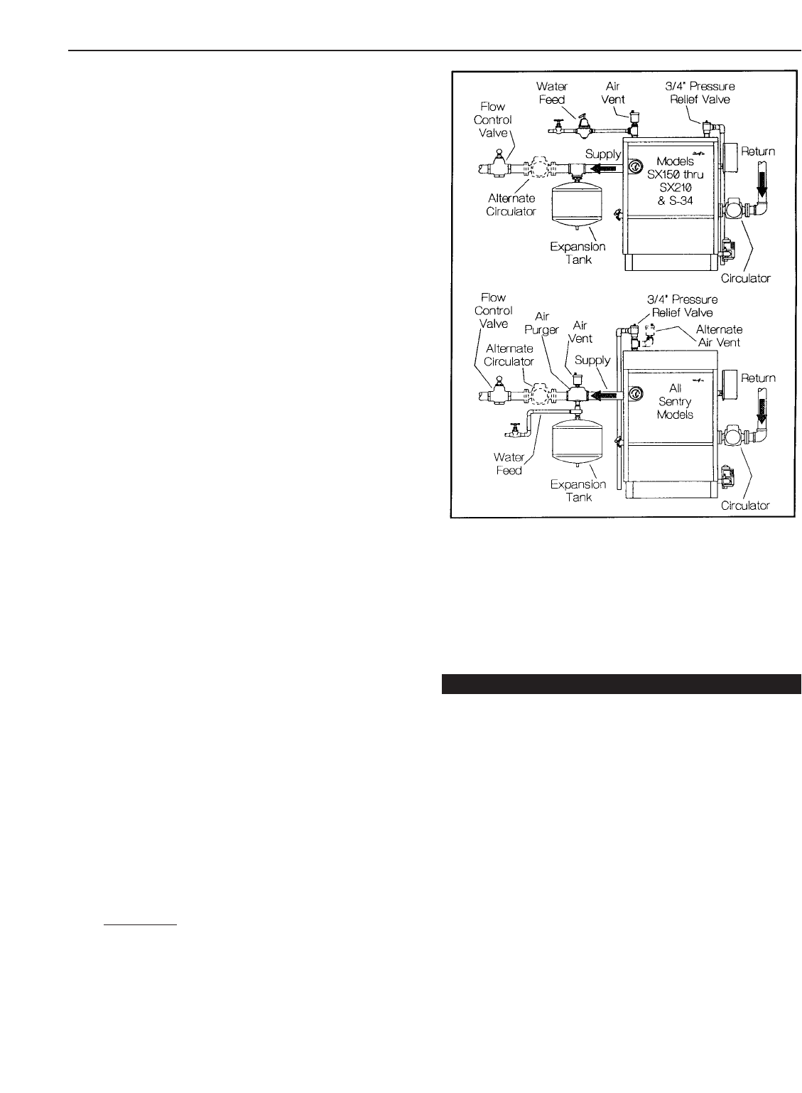
WATER PIPING
I. CIRCULATING SYSTEMS
A. Packaged water boilers are equipped with a water circu-
lating pump, mounted to return the water into the boiler.
For some installations, the pump should be on
the supply main. See figure 10.
II. AIR CONTROL SYSTEM
A. DIAPHRAGM-TYPE COMPRESSION TANKS are used
to control system pressure in an AIR ELIMINATING SYS-
TEM: an automatic air vent is used to REMOVE air from
the system water. See figure 10. If system pressure
needs further control, add an additional tank or install a
larger capacity tank. Locate the tank near the boiler, as
illustrated.An automatic air vent should be installed in the
top of the boiler or air purger. See figure 10.
B. PUMP LOCATION — Locating low-head pump(s) on
return to boiler is acceptable for smaller boiler sizes in
residences of one or tw
o stories. The alternate pump
location shown in illustration is required in large, multi-
story building installations, especially when high-head
pumps are used. The compression tank must be at the
boiler or between boiler and supply main pump(s).
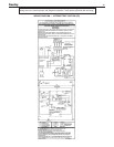
IMPOR
TANT: Hot water heating systems containing high
water volume, such as would occur with cast-iron radia-
tion, require special care with air elimination.
The circulator pump should be located on the boiler sup-
ply pipe and the expansion tank and air scoop should be
located near the pump suction.
C. On a hot water boiler installed above radiation level, the
boiler must be provided with a low water cutoff device at
the time of installation by the installer.
Figure 10. Piping Arrangement
D. Radiant floor and low water temperature systems:
A boiler by pass loop, three way valve arrangement, or prima-
ry secondary pumping (with a boiler loop) must be used to pro-
vide a minimum 130˚F return water temperature to the boiler.
This will prevent condensation on the cast iron sections that
can result in improper operation of the boiler.
I. FILLING AND VENTING WATER SYSTEMS
A. Fill the system with water. Vent or purge off air.
B. Fire the boiler as soon as possible (see following warning
and instructions) and bring water temperature to at least
180 degrees, while circulating water in the system.
C. Vent air and add water as needed to achieve operating
pressure on boiler gauge. Pressure must be between
approximately 12 psi (cold water) and 25 psi (at water tem-
perature setting of high limit control), for boilers equipped
with 30 psi relief valves. Boilers rated for a higher pressure
and equipped with a matching relief valve may operate at a
higher pressure, but no higher than 5 psi below the relief
valve opening pressure.
D. Check for and repair any leaks before placing system in
service.
Before firing boiler, make these checks:
1. System is full of water. Air is vented or purged.
2. Relief valve is installed in accordance with the ASME Boiler
Pressure Vessel Code, Section IV. Valve opening is not
closed or reduced in size.
3. Venting is installed according to instructions under “VENT
PIPING”.
4. All wiring is completed, following applicable wiring dia-
grams.
8
Sentr y
OPERATING INSTRUCTIONS