


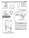
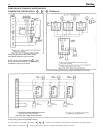
A. Minimum boiler clearances shall be as follows:
B. Provide accessibility clearance of 24” on sides requiring
servicing and 18” on sides used for passage.
C. All minimum clearances shown above must be met. This
may result in increased values of some minimum clearances
in order to maintain the minimum clearances of others.
D. Clearance from hot water pipes shall be 1 inch**.
** At points where hot water pipes emerge from a floor wall or ceiling, the
clearance at the opening through the finished floor, wall or ceiling boards
may not be less than 1/2 inch. Each such opening shall be covered with
a plate of non-comb
ustib
le mater
ial.
SAFETY—
KEEP THE BOILER AREA CLEAR AND FREE FROM
COMBUSTIBLE MATERIALS, GASOLINE AND OTHER
FLAMMABLE VAPORS AND LIQUIDS.
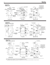
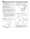
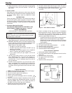
DRAFT HOOD—
The draft hood supplied with SX-150 through SX-210 models is
part of the listed boiler assembly. DO NOT alter the hood. See
dimensions, page 2.
Attach the hood to the boiler flue outlet. Connect flue pipe full
size of hood outlet.Vent damper must be installed on the outlet
side of the hood. See Vent Piping, below.
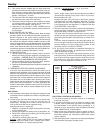
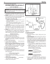
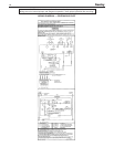
VENT PIPING—
A. Vent piping installation must be in accordance with ANSI
Z223.1-latest edition, National Fuel Gas Code, Part 7,
Venting of Equipment. Other local codes may also apply and
must be followed.
B. Boiler vent pipe must be the full diameter of the boiler outlet.
See dimensions, page 2.
C. If more than one appliance vents into a common breeching,
the area of the breeching must be equal to the area of the
largest vent plus 50% of the area of the additional vent
areas. Vent connectors serving appliances vented by natur-
al draft shall not be connected into any portion of mechani-
cal draft systems operating under positive pressure.
Horizontal breeching or vent pipe should be as high as pos-
sible, consistent with codes, so that vertical vents from appli-
ances will have a high rise above draft diverter openings. All
horizontal runs must slope upwards not less than 1/4 inch
per foot of run. Horizontal portions of the venting system
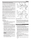
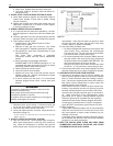
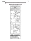
CHIMNEY REQUIREMENTS
A. Sentry boilers may be vented into a masonry vitreous tile-
lined chimney or type “B” venting system NOT EXPOSED to
the OUTDOORS below the roof line.
Venting and sizing of venting system must be in accordance
with Part 7, Part 10 and Appendix G of the National Fuel
Gas Code ANSI Z223.1, NFPA 54, -latest edition which will
be referred to as the National Fuel Gas Code. Local codes
apply.
If a masonry chimney is exposed to the outdoors on one or
more sides below the roof line (exterior chimney), ONE of
the following options apply:
1. Chimney must be re-lined with a metallic liner. When this
is done, the chimney will be considered NOT exposed to
the outdoors and the requirements of the National Fuel
Gas Code for NON-exposed chimneys and/or local codes
will apply.
2. If an exposed tile-lined chimney is to be used WITHOUT
a metallic liner, the boiler must first meet the require-
ments of the following tables and paragraphs of the
National Fuel Gas Code:
I. For Single Sentry Boiler - Paragraph 10.1.9 and
table 10.11.
II. For multiple appliances - Paragraph 10.2.18 and table
10.12 (or 10.13 if applicable).
In addition, all requirements of Part 7, Part 10 and
Appendix G of the National Fuel Gas Code and/or local
codes apply.
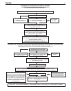
B. If an existing boiler is removed from a common venting
system, the common venting system may be too large
for proper venting of the remaining appliances connected to
the common vent. Follow the test procedure shown in
Appendix “A” on page 19 of this manual to insure proper
operation of venting system and appliances.
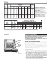
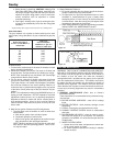
SENTRY SERIES
MINIMUM CLEARANCE FOR COMBUSTIBLE CONSTRUC-
T
ION. MINIMUM ALCOVE AND CLOSET CLEARANCE.
S-34 through SX-150 through
S-150
SX-210
Front 6" 6"
Rear 6" 6"
Left Side 6" 6"
Right Side 12" 12"
Top (above boiler) 12" 28"
Flue Connector 6" 6"
C. Inspect for proper and tight construction. Any restrictions or
obstructions must be removed. An existing chimney may
require cleaning.
D. Chimney or vent must extend at least 3 feet above any
ridge within 10 feet of the chimney.
MINIMUM CLEARANCES FROM COMBUSTIBLE
C
ONSTRUCTIONS
W
ARNING
LIQUEFIED PETROLEUM (L.P.) PROPANE
GAS-FIRED BOILER LOCATION
REQUIRES SPECIAL ATTENTION
Liquefied Petroleum (L.P.) propane gas is
heavier than air.
Therefore, propane boilers, piping, valves should not be
i
nstalled in locations where propane leaking from defective
equipment and piping will “pool” in a basement or other space
below the leak.
A
spark or flame from the boiler or other source may ignite
the accumulated propane gas causing an explosion or fire.
Provide a level, solid foundation for the boiler. Location should
be as near the chimney as possible so that the flue pipe from
boiler to chimney is short and direct.
T
he UNIFORM MECHANICAL CODE may be in effect in
your geographic area
The following precautions are cited by the 1994 UNIFORM
MECHANICAL CODE, section 304.6:
“LPG Appliances. Liquefied petroleum gas-burning
appliances shall not be installed in a pit, basement or sim-
ilar location where heavier-than-air-gas might collect.
Appliances so fueled shall not be installed in an above-
grade under-floor space or basement unless such loca-
tion is provided with an approved means for removal of
unburned gas.”
Consult Chapter 5 of the 1994 UNIFORM MECHANICAL
CODE for design criteria of the “approved” means for removal
of unburned gas.
4
Sentr y