


Simrad Reversible Pump RPU80/160/300
20 20220422N
A clearly formed lip should be visible on the pipe in front of the
cutting ring. If this is not present, the nut should be tightened by
an additional ½ - 1 turn. Check once again as above. From the
T-couplings run a pipe 10x1 mm (US model: 3/8"), to the pump
unit. Avoid high points in the run that could allow air pockets to
form.
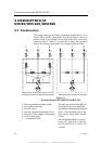
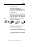
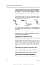
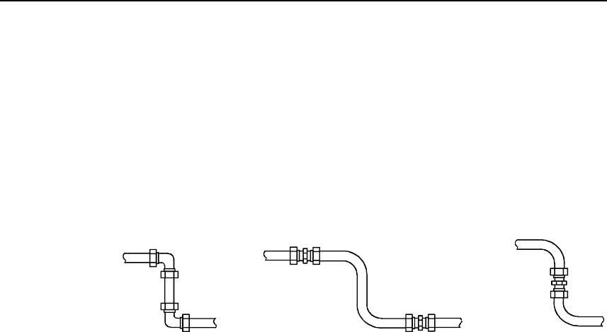
Sharp bends in the pipes (i.e. elbow bends) should be avoided as
these restrict the oil flow. For the same reason couplings should
not be fitted on bends, see Figure 4-4.
Figure 4-4
Pipes should be bent cold. Attempts to use blowtorch and sand
will lead to impurities entering the system, and should therefore
be avoided.
Stop cocks should be fitted to all pipes near the pump unit.
Sluice cocks or similar should be used, and not cocks of the
water supply type. Pipes should be fitted from the stopcocks to
the outlet A and B of the pump unit.
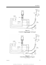
Connection to expansion tank
Most hydraulic steering gears have an expansion tank
incorporated in the steering wheel pump. At the bottom of this
tank is a drain plug, which should be removed and replaced by a
coupling which fits the expansion pipe (10x1 mm, US model:
3/8").Fit a 10x1 mm (US model: 3/8") pipe from the wheel
pump at a uniform, gradual, downward slope to the pump unit.
A stop cock should also be inserted in this pipe near the pump
unit.
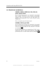
Connection to separate expansion tank
If the steering wheel pump does not incorporate expansion tank,
a separate expansion tank must be installed. This tank should
have a volume of 1/4 liter (0.25 qt), and be placed at
approximately the same level as the steering wheel pump.
Lock valve for steering wheel pump
If the steering wheel pump is not provided with a lock valve
(they most often are), an adequate lock valve should be fitted.
www.Busse-Yachtshop.de email: info@busse-yachtshop.de