


Simrad Reversible Pump RPU80/160/300
16 20220422N
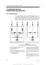
3.3 Valve block
This is an aluminum block with borings for non-return valves,
suction valves, slide, gear pump, motor coupling and all
necessary oil ways. The three outlets A, B and C are positioned
on top of the valve block.
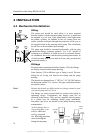
3.4 Gear pump
This comprises of the driving gear wheel, which is coupled to
the motor shaft via a flexible shaft coupling, and meshed with
the driven gear wheel supported by the valve block (1) at one
end and by the pump cover (5) at the other.
The gear wheels run in the pump housing. The gear wheels are
1/100-2/100 mm smaller than the pump housing.
O-rings are fitted to both the valve block and the pump cover to
provide oil tight seals on both sides of the pump housing.
The pump cover is held by 4 screws (25).
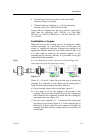
When the gear wheels rotate, oil is carried in the inter-tooth
spaces around the periphery of the pump housing from the
suction side to the pressure side.
3.5 Pressure operated non-return (check) valves
on outlet A and B
These are screwed into the valve block from both sides. The
valve comprise of valve housing (6), plug (7), ball (12), spring
(8), copper washer (17), O-ring (13) and copper washer (14).
The housing and plug are made of stainless steel.
3.6 Suction valves on outlet C
These are connected to both sides of the gear pump via oil ways
in the valve block. The valve comprises of a grub screw (21),
spring (9) and ball (20).
If the grub screw (21) is removed, it should be refitted with
Loctite 542 after degreasing the threads.
3.7 Slide (10)
This is located within the valve block in a cylindrical run
between the non-return valves for outlets A and B. The slide is
grooved to allow location of an O-ring (13).
www.Busse-Yachtshop.de email: info@busse-yachtshop.de