


Simrad Reversible Pump RPU80/160/300
14 20220422N
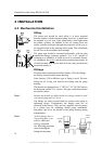
3 DESCRIPTION OF
RPU80/RPU160/RPU300
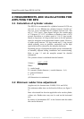
3.1 Construction
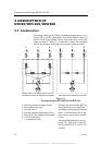
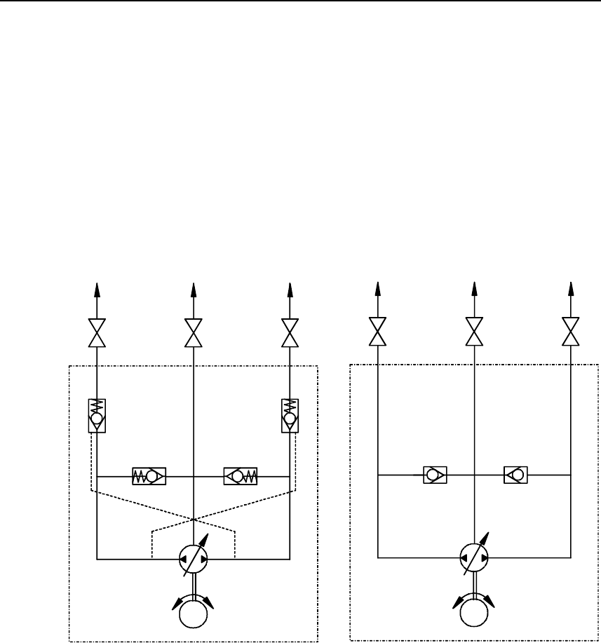
The pump comprises an electric permanent magnet motor, valve
block with reversible gear pump, non-return (check) valves on
outlet A and B and suction valves from both sides of the gear
pump to outlet C. Outlet C is connected to either the expansion
tank in the steering wheel pump or a separate expansion tank.
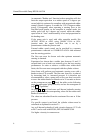
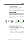
RPU80/RPU160/RPU300 PRINCIPLE DIAGRAM
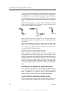
PREVIOUS RPU80 PRINCIPLE DIAGRAM
M
44
667
555
33
2
1
ACB
M
667
55 5
33
2
1
A
CB
Figure 3-1
Principle diagram RPU80/RPU160/RPU300
1. Electric permanent magnet motor
2. Reversible gear pump
3. Suction valves
4. Pressure operated non-return valves
5. Stop cocks (Not supplied with pump)
6. A+B to main pipes
7. C to expansion tank
The previous model of the RPU80
Reversible Pump was simplified
according to the principle diagram
above. It had no check valves and
there was no spring in the suction
valves.
The simplified units have ser. no.
below 1317 H02 (P/N 21116165)
and 1805 H03 (P/N 21116181-US
version).
www.Busse-Yachtshop.de email: info@busse-yachtshop.de